|
|
• PHILCO BEAM-OF-LIGHT PICKUP • | |||||||||||||||||||||
| 1941-1942 Record Changers Setup and Adjustment |
||||||||||||||||||||||
This
article describes the mechanical and electrical alignments for the Philco "Beam-Of-Light" tonearm reproducer as used on the Standard and Deluxe record changers in radio-phono combo consoles from 1941 and 1942.
Not only are there photocell pickup alignments, but also tone-arm
tracking weight adjustments. Individual changer mechanism adjustments are included in the appropriate service bulletins for the Standard and Deluxe changers.
This unique pickup arrangement was used on these models:
1. Place the tone-arm on the tone-arm support, remove the three screws holding the plastic cover on the tone-arm head, and remove the cover.
2. If the exciter lamp is burned out, turn the light adjusting screw on the pick-up head, Figure 1, counter-clockwise, until the lamp socket is in a position to be removed. Remove the lamp socket from the lens barrel, being careful not to break the fibre ends of the socket.
3. When replacing the lamp socket in the lens barrel, twist the socket slightly to prevent creeping of the rubber bushing. NOTE: Always hold the lens barrel with the thumb when inserting or adjusting lamp.
4. Turn the light-beam adjusting screw clockwise
to center the beam within the cell frame. If the beam cannot be drawn to the center of the cell, remove the exciter lamp and rotate it 180 degrees or, as an alternate method, replace it with a new exciter lamp, Part No. 34-2478. The beam should be 5/32" wide. If adjustment is necessary,
back the lamp socket out of the lens barrel approximately 1/4" then slowly press the socket back in until a clear sharp focus is obtained. Should the beam be focused at an angle on the cell, turn the fibre portion of the socket until the beam is vertical.
5. If the beam does not center vertically on the
cell, loosen the two center screws on the jewel and mirror assembly and slide a paper shim in each side between the jewel assembly and the mounting ears. To lower the beam, insert the shims at the bottom; to raise the beam, insert the shims at the top. Tighten the two center screws. If shimming does not correct the trouble, it will be necessary to replace the jewel and mirror assembly, Part No. 318-2641. In extreme cases where replacing the jewel and mirror assembly does not produce the desired results, the tone arm may be bent and will have to be replaced.
6. Turn the light-beam adjusting screw clockwise
until one half the beam is on the side of the cell nearest the spindle. See Figure 1. Replace the plastic cover.
7. Place a record on the turntable and lower the
tone arm until the jewel is seated in one of the grooves. Recheck the position of the beam on the cell. Hook a 2-oz. scale under the nose of the plastic cover and measure the pull required (away from spindle) to move the light fully onto the photocell. This should not exceed 5/8 oz.; a considerably less pull is an indication of loose screws in the jewel and mirror assembly or a defective assembly. More pull will also
indicate a defective assembly and will require replacement of the entire jewel and mirror assembly, Part No. 318-2641.
8. The following test
procedure is a method for testing the sensitivity of the photocell in the pick-up head. The meter emplyed to compile the chart, Figure 2, is the Philco Circuit Tester, Model 020, which is a 5000 ohm-per-volt meter. [NOTE: Newer meters with higher ohms-per-volt specs will show higher readings.]
a. Remove the plastic cover from the pick-up
head and energize the exciter lamp by connecting it to 3 volts A/C from a 6.3 volt filament transformer on a variable transformer, or variac, to bring the lamp voltage to 3 volts. [NOTE: The exciter lamp is rated at 3.3 volts max.]
b. Be sure the light beam is correctly focused
on the photocell, as shown in Figure 1. Measure the exciter lamp voltage and carefully note the reading.
c. Obtain an output reading of the photocell
by connecting a millivoltmeter across the photocell terminals. CAUTION: The a-c voltmeter used to measure the exciter lamp voltage must remain connected to the exciter lamp socket throughout this test.
d. Compare the reading of the exciter lamp
voltage and the photocell output with the chart, Figure 2. The figures on the chart are the MINIMUM readings for a satisfactory photocell.
EXAMPLE: The minimum millivolt output for a photocell
with the exciter lamp operating at 3.0 volts is 42 millivolts (0.042 volts).
9. If the photocell output is low, clean the holder
contacts of the photocell. Remove the two mounting screws, lift the assembly, and release the spring clips holding the cell to the bakelite mount. Remove the cell, holding it by the edges to avoid fingerprints on the sensitized surface. Wipe the cell with a clean, dry cloth, and clean the contact spring. CAUTION: Any cleaning solvents will ruin the cell. Replace the cell on the bakelite mount, and fasten the assembly in place with the two screws.
10. If the output of the cell is still low, replace
with a new cell, Part No. 56-1883.
11. Replace the plastic cover and tighten the three
mounting screws.
NOTE: Do not, under any circumstances, attempt to adjust the angle of the jewel which normally extends 1/32" below the guard. The jewel should be vertical, with respect to the record surface, when viewed from the front of the pick-up head. With one record on the turntable, the jewel will be at an angle of approximately 13 degrees, when viewed from the side. Do not attempt to change the angle, as the surface noise is reduced to minimum by this position of the jewel in the record groove. Any change from the original setting will also affect the frequency response and cause excessive record wear. Replace the jewel and mirror assembly, Part No. 318-2641, if the angle of the jewel has been altered. 
There were three types of tonearms - aluminum, zinc and bakelite. The aluminum tonearm requires a 1-1/2 oz. counterweight, the zinc arm, identified by a yellow paint dot on the underside, requires a 5 oz. weight, and the bakelite arm requires a 3 oz. weight. The weight of all three types of tonearms should be 1-1/2 to 1-5/8 oz. when equipped with the correct counterbalance weight.
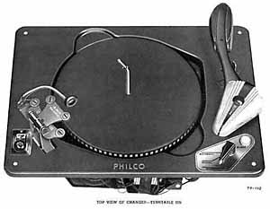
To check for the correct weight, turn the tonearm weight-adjusting screw, see figure, counteerclockwise until all spring tension is released. Hook a 2 oz. scale to the nose of the pickup plastic cover. If the weight of the tonearm does not fall between the minimum and maximum, replace the counterweight with the correct weight to conform.
Again with the scale hooked to the tonearm, adjust the counterweight adjusting screw clockwise until a weight reading of 1-1/4 oz. is obtained. This is the correct tracking weight for each type of tonearm.
For repairs and restoration of your Beam-Of-Light tonearm or pickup, West-Tech Services can do the job!
|
||||||||||||||||||||||