BK oscilloscope model 1405 test leads?
Posts: 264
Threads: 51
Joined: Aug 2014
City: San Antonio, TX
Somewhere along the line, I have come into possession of a BK 1405 oscilloscope. It sort of works, but I've never done anything thing to it or with it because of two reasons:
1) I haven't recapped it, yet, and
2) I have no test leads.
I have powered it up about a year ago, and it seems to work (it puts a sine wave on the CRT at least). It has what seem to be banana plug sockets where the test leads go.
I confess to absolute ignorance about the use of an oscilloscope in radio repair, but I'd kind of like to learn about it. Can anyone suggest the proper test leads for this model? I'm sure I can find the appropriate chapter in Levy's book or some radio repair course for instruction on how to use it.
BTW, I do NOT have a signal tracer, yet. SO that is on the "get" list soon.
Charlie in San Antonio
Posts: 1,113
Threads: 14
Joined: Feb 2013
City: Irvington, NY
Charlie, the 1405 is a fairly modern solid state oscilloscope. I would not consider any recapping unless there is an obvious problem. Most likely the only service it will need is a cleaning of the pots and switches.
Here is a link to the service manual:
http://elektrotanya.com/bk-precision_140...nload.html
You can use a simple shielded cable with alligator clips as test leads.
The user manual gives some basic info on how to use it:
http://bee.mif.pg.gda.pl/ciasteczkowypot...Manual.pdf
Posts: 264
Threads: 51
Joined: Aug 2014
City: San Antonio, TX
Thanks for the test lead solution. Now, the education starts. Maybe I can use it to track down the source of the hum and interference on the 41-280. Good reception, plenty of selectivity, but the sound is distorted and off station hum.
Charlie in San Antonio
Posts: 1,113
Threads: 14
Joined: Feb 2013
City: Irvington, NY
Yes, you can use the oscilloscope as a signal tracer to find problems in the audio circuitry. Here are a few ideas.
If you are uncertain of the voltage level at a point you are testing, make sure the attenuator of the scope is at the 1/100 setting and AC coupled. This will prevent damage to the scope and overload. If you do not see the signal, you can reduce the attenuation to 1/10.
Start at the detector output ( top end of volume control ) and look at the signal from a signal generator modulated with a sine wave tone. You should see an undistorted sine wave there. Then go to the output of the first audio stage and you should see the same waveform only larger when the volume control is advanced. Proceed stage by stage until the output. If at any point the sine wave becomes distorted, then concentrate on that circuitry as the cause of the problem.
You can also see the level of hum on the power supply with the scope. Just make sure it is AC coupled an use the 1/100 attenuator setting.
Once you learn how to use it, the oscilloscope becomes a very valuable tool in signal tracing and troubleshooting.
Posts: 264
Threads: 51
Joined: Aug 2014
City: San Antonio, TX
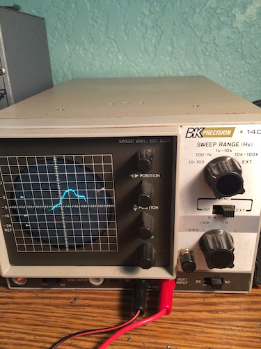
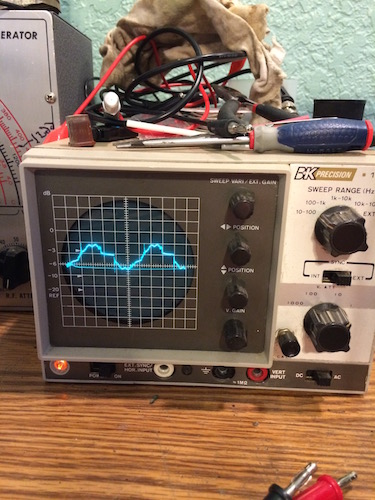
OK. Hopefully I can figure things out from here, but I wanted to ask one more question if I may. I have my new shielded test leads in place. I got two: one with a 100Hz probe and another with two alligator clips. With the probe attachment or the alligator clips plugged in and not actually testing anything (just lying on the bench), I get this sine curve on my screen with the scope set as shown (all the lowest settings of sweep range of 10-100 and v. att of 1 and AC). Is this what I should be seeing, or shouldn't the curve be a smooth curve? My camera only caught one part of the curve, but my eyes see it repeating on the screen. Do I have some adjusting to do, or am I seeing the electrical interference that my house is prone to (ALL of my tube radios have Rf noise from about 1000-1700 on the dials.

Charlie in San Antonio
Posts: 1,113
Threads: 14
Joined: Feb 2013
City: Irvington, NY
Yes, it looks like you are seeing the electrical noise and hum present in your house. Thing is, if the cable is shielded and properly grounded, you should not be seeing all that noise.
How do you have the shield connected? The inner conductor should connect to the red terminal, and the shield to the black. If the shield is not grounded and left floating, then you will pick up all sorts of hum and noise.
Posts: 264
Threads: 51
Joined: Aug 2014
City: San Antonio, TX
I bought the test leads from Amazon. In order to get around the banana plug requirement on my scope, I bought three separate parts (four counting the two different test lead parts): a banana plug lead (black and red plugs) that ends in a male coaxial plug, a female to female coaxial connector, and the two test leads both with male coaxial plugs. I would assume they were properly made, but after reading your post, I turned off several things in the house, and looked at it again. It got only a bit more smooth, and responded to my touching the connector part, so I'm guessing that means the connectors are not properly grounded. I guess I'm in the market for a better female to female connector. Or a banana plug to female coax jumper cable.
Charlie in San Antonio
Posts: 264
Threads: 51
Joined: Aug 2014
City: San Antonio, TX
I've figured out that my problem is grounding or shielding inside the scope itself. I don't know why it didn't occur to me to try it with no leads on, but I get the same sort of sine wave with no leads that I get with the leads in place. It isn't the mains. I've tested them and they are grounded correctly.

Charlie in San Antonio
Posts: 1,113
Threads: 14
Joined: Feb 2013
City: Irvington, NY
If you short the red and black terminals together on the scope input, does the hum and noise waveform go away?
Is the scope chassis grounded through a 3 prong AC cord?
Posts: 264
Threads: 51
Joined: Aug 2014
City: San Antonio, TX
According to a visual inspection of the scope, the green ground wire is taped up and secured to the side of the power transformer without making contact with anything. According to the schematic, there is no green ground wire at all, correct? It looks to me like the transformer grounds to the chassis? Ground appears on the schematic as coming out of the transformer on the side.
But...why would this scope have a three-prong cord at all if it makes no use of the green wire?
Little change when I short the leads.
I cleaned the pots and switches and saw no real improvement, either. I also gently moved a few wires that were making contact with parts of the sweep switch. Nothing.
It looks like one of the grounds isn't making good contact, then? I guess I'll start tracking them down.
Charlie in San Antonio
(This post was last modified: 09-04-2015, 04:24 PM by ccomer1955.)
Posts: 1,113
Threads: 14
Joined: Feb 2013
City: Irvington, NY
Try connecting the green ground wire to the chassis. Although not shown on the schematic, the manual mentions that the chassis and case of the scope is grounded with a 3 wire cord. See page 2, paragraph 7 of the service manual "test instrument safety"
Some previous owner probably " lifted " the ground by disconnecting the green wire, so they could work on "hot chassis" sets without an isolation transformer. This is a very dangerous practice and should never be done.
Posts: 264
Threads: 51
Joined: Aug 2014
City: San Antonio, TX
Must have done, and he has caused other problems as well it seems. Under the tape, the green wire had an eyelet connector that fits perfectly over a small bolt in the chassis with a lock washer and nut on it. Right by the transformer. I put it on and locked it tight. The sine wave is much noisier, now, so I'm sure I will need to track down other issues on it. However, if it helps, when I have the alligator clip lead on it and touch the black and red together the curve flattens to a straight line.
Charlie in San Antonio
Posts: 1,113
Threads: 14
Joined: Feb 2013
City: Irvington, NY
Well you are making progress. If the hum waveform flattens to a straight line when you short the input, then you are on the right track. It looks like you are just picking up noise from the unshielded portions of the probe or input wiring.
How about when you have nothing plugged into the input terminals? Do you still get the hum waveform when the case is installed? Without the shielding of the case, you may get noise pickup from the sensitive preamp circuitry of the scope input.
Posts: 264
Threads: 51
Joined: Aug 2014
City: San Antonio, TX
Interesting results: with no leads in place, I'm getting a flat line for the most part. If I turn the v gain pot, it momentarily shows a spiked sine wave, then flattens. I get similar results with the 10x probe in place. Jiggling or turning the v gain pot gives me a spiked sine wave that settles down to a flat line with the probe plugged in or without. With it plugged in, I of course have the probe connected to no electrical source at the probe end.
So...really dirty pots?
Charlie in San Antonio
Users browsing this thread: 1 Guest(s)
|


