Thread Rating:
  • 0 Vote(s) - 0 Average
  • 1
  • 2
  • 3
  • 4
  • 5

41-616 restoration
#1

Ron, 

I really enjoy reading this thread [edit by moderator: the thread referred to here was in the Restoration Notes section] as i just started on my 41-616 tonight still cleaning it, there were mice,yuck.  But have been looking over the capacitors and trying to figure out new ones to order, and im stumped.

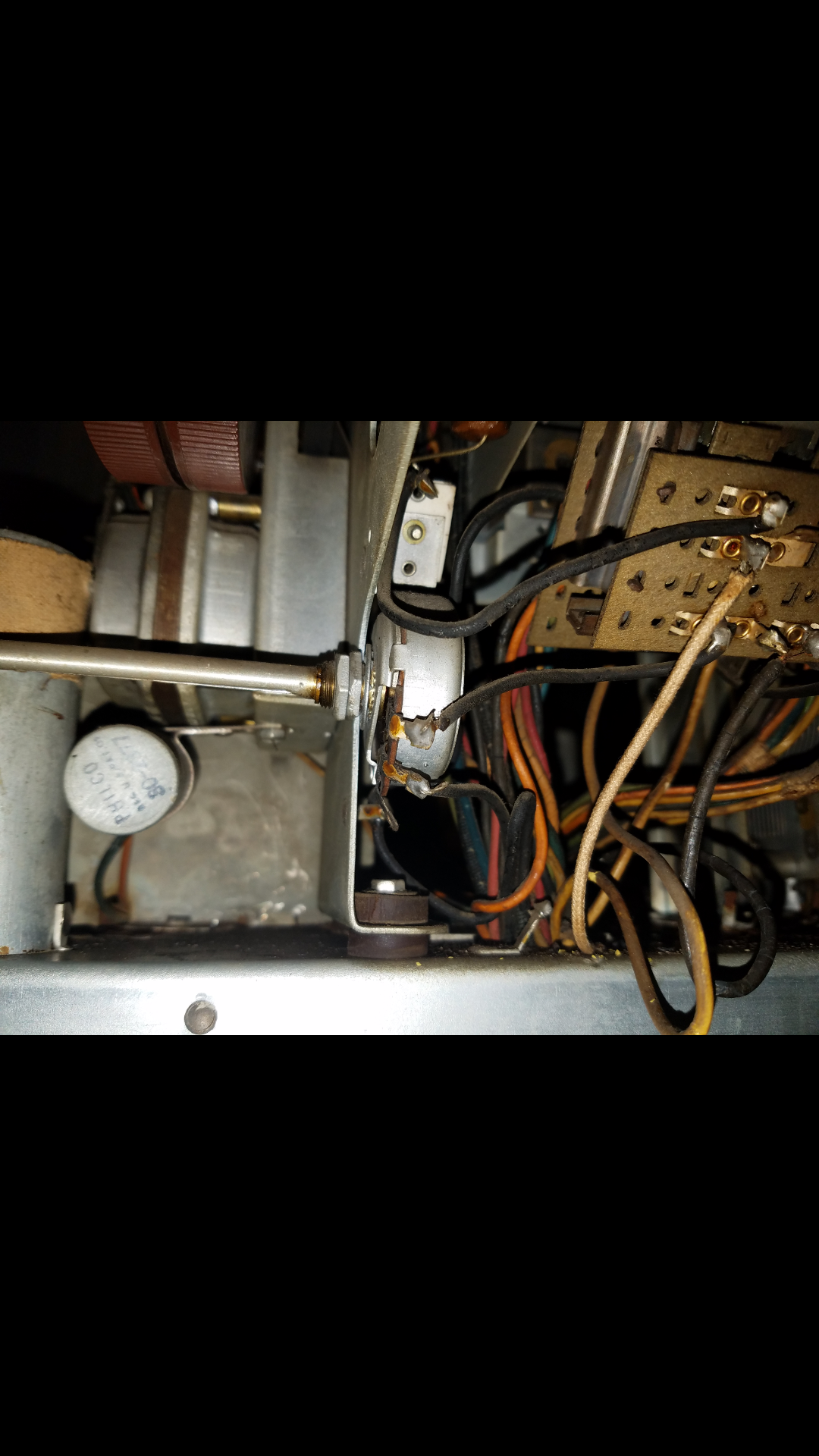
 First what is the voltage on the 30 mfd electrolytic one (philco 30-2377) that was mounted to the bottom of the volume motor? Is it a non polarized one like the 16 mfd? And why did yours wind up being so large is there something really special about it?

Also the why is the 125mfd capacitor number 100 on the parts list 25mfd on the schematic? How can there be such a discrepancy between the parts list and the schematic?

Also on the schematic and parts list a condeser is listed as being in the power plug, but no values are given can you give any insight on this? And also on what fuses to install on power cord? 

Finally on my radio theres an unusual added potentiometer clamped to the front of the chassis and wired into the left most pushbutton, any ideas?

  Photo shows potentiometer and capacitor attached to motor.

Thanks 
Ryan
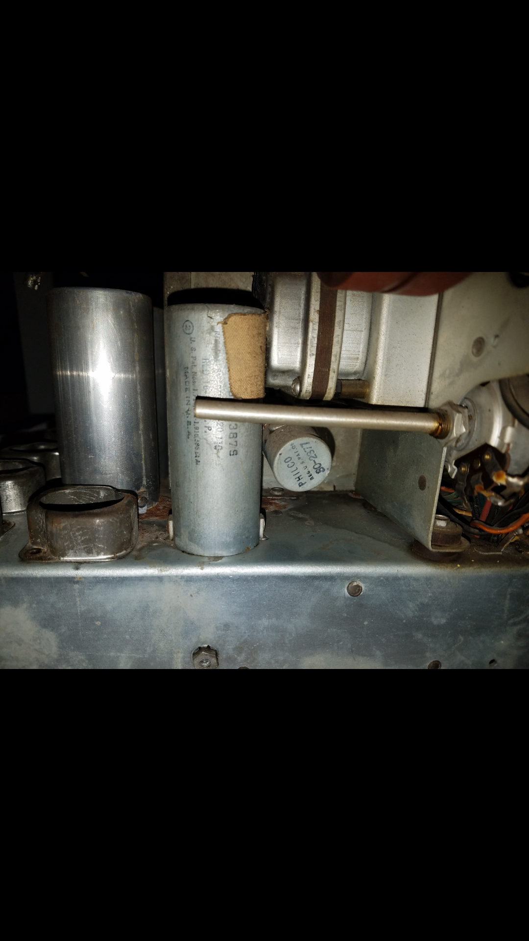


Please see attached photos.
#2

This thread was started in the Restoration Notes section and has been moved here since it fits better here now that the restoration has started. Thanks!
#3

Ok thanks
#4

Bob - thanks for moving this thread Icon_thumbup

Ryan - I haven't owned the 41-616 in some time now, so I don't remember all of the details.

> First what is the voltage on the 30 mfd electrolytic one (philco 30-2377) that was mounted to the bottom of the volume motor?

As I said, I don't remember. I don't have the service data in front of me.

(looking at Nostalgia Air)

Hmmm, the schematic is stingy on voltages. Something probably in the neighborhood of 50 volts would probably work...but check the AC voltage going to the motor to be sure.

> Is it a non polarized one like the 16 mfd?

Yes.

> And why did yours wind up being so large is there something really special about it?

I think at the time I was looking for something that would fit the clamp, and the cap I installed fit perfectly. If I did it again I would have gutted the original can and put a new cap inside.

> Also the why is the 125mfd capacitor number 100 on the parts list 25mfd on the schematic? How can there be such a discrepancy between the parts list and the schematic?

No idea. Philco did make mistakes when drafting their schematics at times. The NA schematic is hard to read but I think (100) is coming off the output end of the filter choke (99)? If so it would surely be 25 uF, not 125 uF. Look at the original part to be sure (if it is still there).

> Also on the schematic and parts list a condeser is listed as being in the power plug, but no values are given can you give any insight on this?

'Fraid not, sorry. I replaced the power cord and plug on that 41-616 when I had it, and did not bother with a cap. If it makes you feel better, install an X1/Y2 safety cap across the AC line inside the radio chassis. I would suggest .0047 uF.

(Come to think of it, I might have installed one of these as well. I honestly do not remember.)

> And also on what fuses to install on power cord?

It did not have fuses originally. The radio is rated at 200 watts @ 118 volts AC. If you want to use a fuse, I suggest a 3 amp fuse. 2.5 amp might not be enough with radio and phonograph in operation and taking the operation of the volume control motor and stepper unit into consideration.

> Finally on my radio theres an unusual added potentiometer clamped to the front of the chassis and wired into the left most pushbutton, any ideas?

nope...very strange, it certainly should not be there. I would remove it and return the circuit to original per the schematic.

--
Ron Ramirez
Ferdinand IN
#5

Hello all i have been working to remove some rust from my philco 41-616 chassis using naval jelly.


My first question is what do i need to clean the chassus with now to neutralize the jelly and prevent any residue eating the paint im about to apply?

Also my plan is to use either rustoleums rusty metal or clean metal primer as theres only some deep pitting left. Then use their aluminum color enamel pai t as a top coat.  

Question 2 for this level of rust is the rusty metal or clean metal primer better/whats the difference?

And question 3 is it really neccesary to prime it? In my little experience the primer almost makes it easier to scrape the paint off. Any thoughts? Or is it ok to just maybe dab some primer on the pitting and apply the paint directly to the metal? Will it stick well enough or will it peel, crack, scrape or flake off more?

Any help would be greatly appreciated!


Attached Files Image(s)
       
#6

I merged the two 41-616 electronics/chassis threads to keep the topic together.

I've only fully painted one chassis and it was pretty badly rusted.  I just rinsed the naval jelly area well, wiping with wet paper towel a number of times.  Then I primed entire chassis with rusty surface primer and followed with aluminum (i think) colored rustoleum.  

Looked ok, not great.  On less rusted chassis i just paint the derusted area with a thin wash of paint trying to mimic the color of the original areas of the chassis.  If i can locate it, i'll add a link to my thread later today.  Remember for components that need chassis contact for ground or B- you can't paint that.

This isn't the thread i was thinking of but has a mix of things i mention above:
http://philcoradio.com/phorum/showthread.php?tid=8715

Naval jelly is acidic, containing phosphoric acid, sulfuric acid among other things so adding a little baking soda to your rinse water would further help neutralize the jelly as well.
#7

Thanks for the responses guys!

Ron, 
Definitely appreciate the advice on the safety cap and the fuses had no idea what I should use also on that 30mfd cap was polarized. Unfortunately for that one capacitor the 25 it must have been 25 not 125 then. Unfortunately it was already replaced but it was replaced with a 20 + 20 so it must have been replacing that 25
Thanks for moving the threads and also for the advice on using the baking soda Klondike 98!
#8

I noticed on one of the other threads that the earlier 39-116 and 40-216 used a 30 uF, 30 volt cap for the volume motor. As you'll find here, Philco changed the cap from 30 uF to 45 uF at some point.

--
Ron Ramirez
Ferdinand IN
#9

Hey All,
 Trying to get back at this project after many months hiatus.  but need to ask what wattage resistors I should be using to replace the Candohm ones mounted to the chassis? or in general, if there is any that need to 1 watt or higher or should I mostly be using 1/2 watt or 1-watt resistors as a whole?  I understand it depends on the voltage and resistance but am unsure what my bare minimum should be and if there's any that in particular need to be high wattage.  

Thanks 
Ryan
#10

Philco, like any other manufacturer, used parts such as that candohm for a reason, if they could have used half Watt resistors in it's place they would have since they are cheaper. I would guess that the resistors in the candohm are at least 3 Watts if not larger, but 5 and 10 Watters are cheap enough to use as replacements, and offer a little more headroom. You also have to remember that the candohm was using the chassis as a heat sink, so if you use free standing resistors it would be wise to use ones of a higher Wattage, for the larger Wattage ones you could go chassis mount like those gold and black ones with the aluminum body.
Regards
Arran
#11

trying to order capacitors and have come across a bit of a question.  on the parts list both the 45MFD motor capacitor(#110) and the 16MFD Can (#115) are shown as regular capacitors on the schematic but are clearly electrolytics.  the motor cap I know is nonpolar/bipolar but is the 16MFD also non-polar/bipolar?  it has red and black wires leading from it giving the appearance it is polarized but nothing else indicates that it is and the can is labeled 16-150-NP making me think NP = Non Polar.  

is this correct? 

Thanks in advance. 
Ryan
#12

also I need to know if I need to also order resistors for this radio and if so how many/to what extent? and what wattage. I know I need to replace the Candohm ones because those fail but beyond those how much do I need to replace?
#13

Since no one has piped in on this I will...

I'm not 100% certain but I believe you can use a nonpolar cap for that 16uF. Antique electronics sells a solen film nonpolar cap @ 22uF that should work.

I measure the resistors in sets I'm restoring and replace those that are >20% off. Some folks replace them all while they are under the chassis. For the most part 1/2 watt resistors will do the trick but as Phlogiston mentioned in another thread recently, 2 watt resistors are readily available and can easily be used. The size of the original resistors gives you a hint at the wattage. Except for candohm and wirewound they would not usually be larger than 2 watts.
#14

Thanks klondike98, 
I looked that cap up and it's apparently $13! is it possible to use a standard 16UF electrolytic polarized Cap? since those are only about $3.  
#15

6.2uf film capacitors are a available at a reasonable cost. You can use three in parallel and not have to worry about replacing them again.

Steve

M R Radios   C M Tubes


Users browsing this thread: 1 Guest(s)