From page 460:

![]()
From page 486:

D. Van Nostrand Company, Inc. 1947
Excerpt from Chapter 7, F-M Detectors
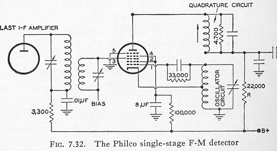
The Philco Single-Stage F-M Detector. There has recently appeared an F-M receiver which utilizes a locked-in oscillator in a manner somewhat similar to the Beers receiver. However, due to the nature of the feedback between the mixer section of the unit, and the oscillator, no discriminator is required. Instead, the audio output is obtainable directly from the plate-current variations of the mixer tube.

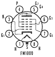
The basic circuit of the F-M detector is shown in Fig. 7.32. The tube, which was specially designed for this purpose, is a heptode. The cathode and the first two grids serve as an electron-coupled oscillator with grid 2 as the plate. Grids 2 and 4 are connected together, but both grids are at I.F. ground potential. The input I.F. signal is fed in at grid 3, whereas the feedback or quadrature circuit is connected to the plate of the tube. Both the oscillator and the quadrature circuit are resonant to the I.F. In order to insure the proper kind of feedback, the quadrature circuit is damped with a relatively low resistor (4700 ohms) so as to have a bandwidth which is roughly six times that required by the F-M signal.
The oscillator grid is closest to the cathode and it will exert the greatest influence over the flow of electrons. The oscillator functions class C and permits electrons to flow past grid 1 only in short pulses. Throughout the remainder of the cycle the grid is biased beyond cut-off. The second controlling element in the tube is grid 3. Its voltage will determine how much of the pulse passed by the first control grid reaches the plate. There are thus two factors controlling the amount of plate current that flows to the quadrature circuit. As we shall see presently, it is through this dual control that the circuit is able to function.
The basic operation of the circuit depends upon the fact that the pulses of current that the oscillator grid permits to flow is further modified in magnitude by the second (or signal) control grid 3. If, at some instant, the potential of grid 3 is more positive than its normal value, an increased plate current will flow through the quadrature coil. Conversely, if grid 3 is more negative, less than the average current will flow. Through the intersection, of the oscillator and the quadrature coils, the change in current will alter the frequency of the oscillator. From the oscillator frequency variation, F-M demodulation occurs. Essentially, then, lock-in between the oscillator and the frequency variations of the incoming F-M signal must occur. In this respect, the circuit is similar to the Beers receiver. However, here the similarity ends.
The circuit consists of three main sections: the oscillator, the quadrature circuit, and the second control grid (No. 3) where the incoming signal is applied. The oscillator is a Hartley, designed to generate a frequency equal to the center frequency of the I.F. band. This is in the absence of any signal voltage. However, when a signal appears (assume for the moment that it is not modulated) , the oscillator adjusts itself to lock-in with the signal. Throughout the lock-in range, the frequency of the oscillator and the signal will be identical.
The lock-in of the oscillator is brought about by the transfer of energy (coupling) between the oscillator coil and the quadrature coil. The quadrature coil is designed so that its impedance does not appreciably change over the range of frequencies of the incoming signal. To insure this, the coil is made to possess a bandwidth approximately six times that which is actually required. This is the reason for the low-valued damping resistor (4700 ohms) .
The quadrature coil is inductively coupled to the oscillator and any change in plate current in the quadrature circuit is reflected immediately into the oscillator. The reflected impedance consists of two parts, a resistive component and a reactive component. The resistive loading remains constant because of the low-valued resistor; The reactive component, however, will vary directly with the plate current. It is this reflected component which causes the oscillator frequency to vary. It is important that only the reactive feedback vary; otherwise, the amplitude of the oscillator signal will fluctuate producing an additional A-M component which is not part of the original signal.
The incoming signal controls the flow of plate current and this, in turn, because of the quadrature circuit, affects the oscillator frequency and causes it to lock-in with the incoming signal. The oscillator frequency is thus kept the same as the signal.
 |
|
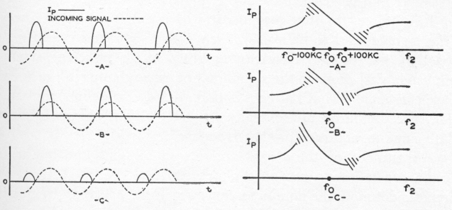
| FIG. 7.33. Interation between the signal voltage and the oscillator pulses to regulate the oscillator frequency. In (A) the two signals are identical; in (B) and (C) the signal frequency is either slightly higher or lower than the oscillator. | FIG. 7.34. (A) The proper response characteristics from the demodulator. (B) and (C) are the result of an improper adjustment. |
The control of the plate current by the signal grid (No.3) is illustrated in Fig. 7.33. In A of Fig. 7.33, the incoming signal has the same frequency as the oscillator and the pulse of current passes through the tube when the signal grid is going through zero. Under this condition the two frequencies are locked together and the average plate current (of the pulses) is such as to maintain this condition. If, upon application of the signal, the exact phase relationship between the signal and the oscillator pulses is not as shown in Fig. 7.33A, then the average value of the plate current will change sufficiently to swing the oscillator into line. Thereafter, the two are locked in synchronization and the situation shown in Fig. 7.33A prevails.
When the signal frequency changes frequency — with modulation — the phase of the signal voltage (with respect to the pulses of plate current) changes, either increasing or decreasing the average value of the current. This change, reflected in the oscillator circuit, appropriately increases or decreases its frequency to the new value. When the new frequency is attained, the phase between signal voltage and oscillator is again as shown in Fig. 7.33A.
Now the question is: How do these variations in oscillator frequency bring about demodulation of an F-M signal? Simply this — the average value of the current over any cycle is directly proportional to the peak value of the fundamental component of the pulse. (A pulse will contain a strong fundamental and many weaker harmonics. The fundamental, of course, is the oscillator frequency.) Now, if the signal frequency rises, so will the oscillator frequency and the average value of the plate current will change. In this circuit, the current decreases. See Fig. 7.34. Conversely, if the signal frequency decreases, the oscillator frequency will decrease. This time Fig. 7.34 indicates that the plate current rises. Thus, plate current will vary with frequency and the circuit is designed so that the current varies in a linear manner (see Fig. 7.34). By placing a resistor in the plate lead, R of Fig. 7.32, we can obtain an audio voltage to feed the audio amplifiers that follow.
Note that the entire action will prevail only so long as the oscillator is locked-in with the incoming signal. If the signal voltage is too small (below one-half volt for full 75-kc deviation) or the signal frequency shift too large, then the oscillator will slip out of control and return to its free-running frequency. This is shown in Fig. 7.34 by the series of broken dashes at the extremes of the discriminator response curve. An advantage of the requirement of a minimum voltage needed for control of the oscillator is the elimination of interstation noise. This is common with the conventional limiter discriminator arrangement. Its disadvantage is the loss of control that may occur with weak signals. However, weak signals tend to be noisy (even with F-M) and therefore the loss may not be too disadvantageous. With sufficient strength, amplitude variations in the signal do not cause change in the average plate current. What happens is that with a change in signal amplitude, the oscillator phase readjusts itself slightly to maintain the plate current required for that frequency.
Adjustment of the circuit consists in aligning the quadrature circuit for a linear response characteristic, Fig. 7.34A. If the circuit is detuned, the nonlinear curves of Figs. 7.34B and 7.34C are obtained.
Excerpt from Chapter 13, Commercial F-M Receivers:

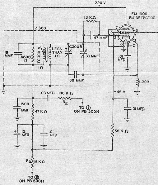
The Philco F-M type of detector, using the specially designed F-M 1000 tube, follows the third I.F. amplifier. It is the same detector which was described in Chapter 7. Plate-current variations, due to the fluctuations in oscillator frequency, produce the demodulated audio voltage across the 47,000-ohm resistor in the plate circuit of the F-M 1000 tube. The output is taken through a 0.03-mf condenser and 100,000-ohm resistor to the F-M push button and from here to the 2-megohm volume control. B+ voltage is applied to the various electrodes through the F-M push button and is active only when the switch is on.
Selected* excerpts for comparison from scanned pages graciously posted by Sylvain on January 3, 2002. Note that the EICO document has many inconsistencies and omits setting for 14Q7.
| TUBE | SHUNT | FIL. | SEL. | UP | DOWN | BASING |
|---|---|---|---|---|---|---|
| 6BA7 | 19 20 |
6.3 | 3 1 |
1, 2 1, 6, 7, 9 |
3, 4, 6, 7 2, 3, 4 |
8CT |
| 6BE6 | 22 22 |
6.3 | 2 2 |
1 5, 6, 7 |
2, 3 2, 3 |
7CH |
| 6BY6 | 25 | 6.3 | 2 | 1, 5, 6, 7 | 2, 3 | 7CH |
| 6CS6 | 25 | 6.3 | 2 | 1, 5, 6, 7 | 2, 3 | 7CH |
| 6L7 | 56 25 |
6.3 | 2 2 |
4 3, 5, 10 |
2, 8 2, 8 |
7T |
| 6SA7 | 24 28 |
6.3 | 2 | 4, 5 3, 4, 8 |
2, 6, 8 1, 2, 6 |
8R/8AD |
| 6SB7 | 22 19 |
6.3 | 2 1 |
4, 5 3, 4, 8 |
1, 2, 6 2, 5, 6 |
8R/8AD |
| 7Q7 | 46 25 |
6.3 | 2 | 2, 5, 6 3, 4 |
1, 7 1, 7 |
8AL |
| 12BE6 | 22 22 |
12.6 | 2 2 |
1 5, 6, 7 |
2, 3 2, 3 |
7CH |
| 12CS6 | 25 | 12.6 | 2 | 1, 5, 6, 7 | 2, 3 | 7CH |
| 12SA7 | 29 42 |
12.6 | 2 2 |
4, 5 3, 8 |
2, 6 2, 6 |
8R/8AD |
| 12SY7 | 32 26 |
12.6 | 2 2 |
1, 3, 8 4, 5 |
2, 6 2, 6 |
8AD |
| FM1000 | 11 | 6.3 | 1 | 2, 5 | 1, 3, 7 | FM1000 |
*Selection criteria:
Based on the theory of operation as described in Kiver, the 6BN6 gated-beam discriminator.