Welcome Guest! Be sure you know and follow the Phorum Rules before posting. Thank you and Enjoy! (January 12) x

Thread Closed
Thread Rating:
  • 0 Vote(s) - 0 Average
  • 1
  • 2
  • 3
  • 4
  • 5

GE A-70 vernier operation
#1

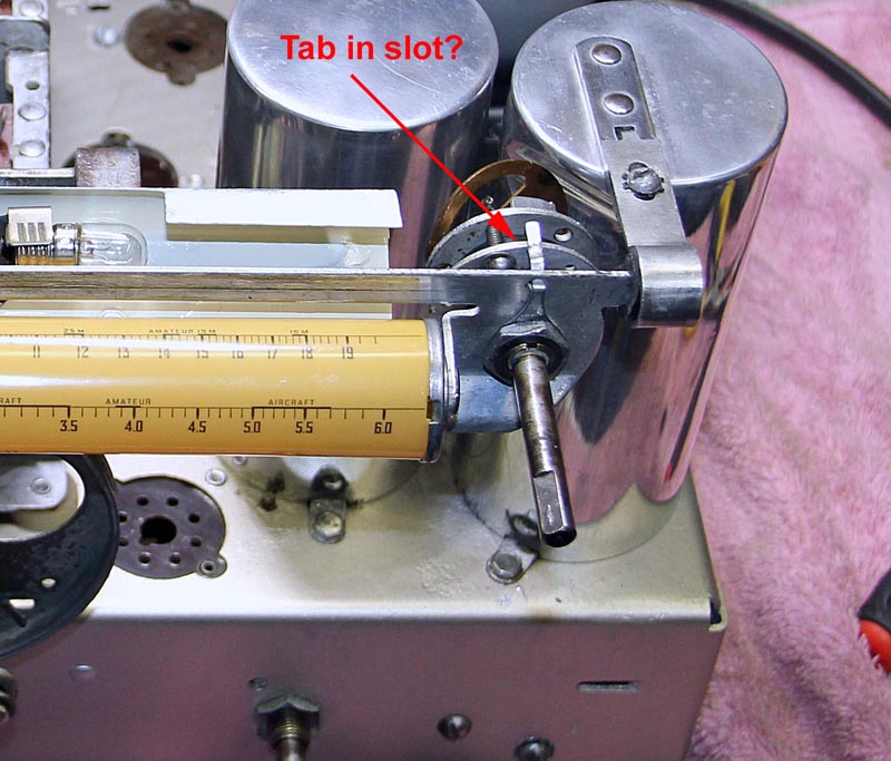
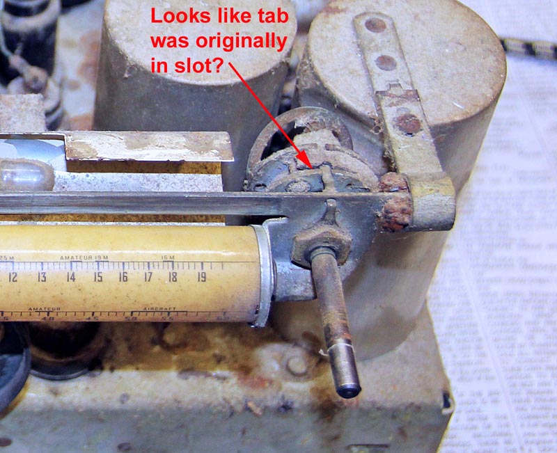
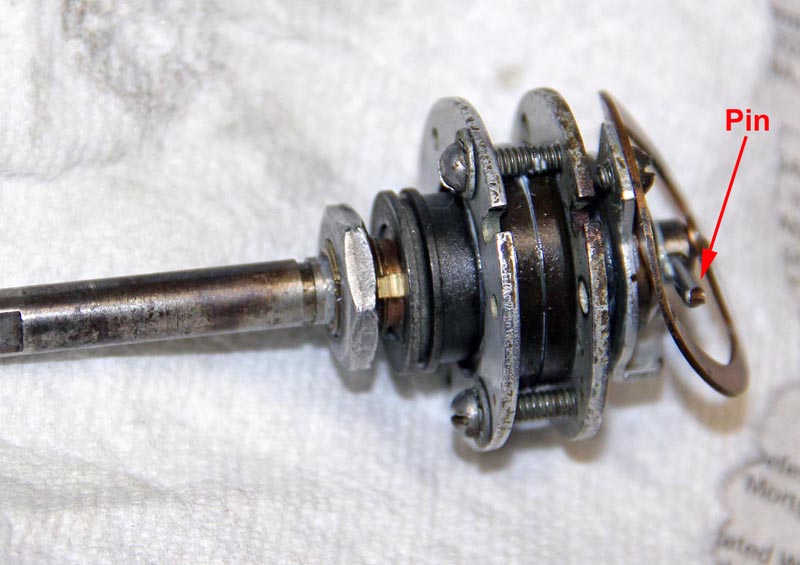
I am having trouble understanding the operation of the vernier control on my GE A-70. I took it apart and cleaned, lubricated it and re-installed it with along with re-stringing the rotating dial. Everything works great except the pointer does not move during fine adjustment. There is only one shaft which I think should automatically switch from fine to coarse when the pin hits the stop on the rear of the control (I attached photos showing the pin and tab).

If I place the tab on nut into the slot on the front of the vernier it prevents the control from switching to coarse and limits the dial travel.  However it appears from my photo of the original set up that the tab is in the slot so I am confused. can anyone shed some light on how this control is supposed to be set up.

Thanks,

Steve D
           
#2

The tab does look like it belongs in the slot. I see a snap ring in the original photo. Was that just holding what appears to be a dust cover or is something possibly missing?
#3

Thanks for you response. I don't see a snap ring and don't remember one when I took it apart.  What appears to be a dust cover I think was actually some dust itself.  The whole vernier was clogged up with dust.

Steve D
#4

I solved this issue by adjusting the three clamping screws to get the proper preload on the ball bearings. I had the screws tightened down too much. The tab does indeed need to be in the slot to prevent rotation of the vernier body and then the screws adjusted for proper operation. This vernier control is intuitive and works very well when adjusted properly.

Steve D


Users browsing this thread:
[-]
Recent Posts
Zenith H725
The PSU filter cap arrived today (thank you USPS!) so I will work on that later. Meanwhile, I have the dial, speaker...EdHolland — 06:42 PM
Philco 610B oscillator wiring
Thanks Terry. After checking my notes I think I recorded about -10v at the 6A7 G4/control grid. The screen grid (G3 &...Tubester — 05:59 PM
The list of my radio & TV collection!
Magical chords of forgotten melodies, old nostalgic music on an old radio... Saturday night blues on the Mid-Waves on an...RadioSvit — 12:20 PM
Philco 42-345 Restoration/Repair
Thank you MrFixr55 the issue with this radio is that the internal coil antenna is missing and there was a wire in its pl...osanders0311 — 11:34 AM
Philco 610B oscillator wiring
Regarding the oscillator circuit which is comprised of the 6A7's cathode, control grid, and screen grid. These elements ...Radioroslyn — 10:33 AM
Philco 42-345 Restoration/Repair
Hi OSanders, First off, welcome to the Philco Phorum where Phine Phamily-Phriendly Pholks Phull of Philco Phacts and P...MrFixr55 — 08:41 AM
Philco 42-345 Restoration/Repair
Today I've been reading through the site trying to learn more about this radio. I also soldered the lose power cord cabl...osanders0311 — 08:24 PM
Philco 610B oscillator wiring
Thanks David! I do have that same later prodution model 610 schematic. I've also studied the Philco service bulletins fo...Tubester — 08:12 PM
Philco 610B oscillator wiring
Some info from Beitmans says late production. David   David — 06:06 PM
Restoring Philco 96
Oh wow! Just found this thread.  Brings me back to early days on this phorum.  I did a 96 back in 2017.  Thread here: ...rfeenstra — 06:05 PM

[-]
Who's Online
There are currently 2402 online users. [Complete List]
» 1 Member(s) | 2401 Guest(s)
Avatar

>