I decided it's time to post something new.
Here's a follow up on the mods to the not so desirable circuit design of this Peerless/Clinton 139. First is the original detector design.

So because there is no AVC the volume goes all over the place. I am thinking can I add AVC to this circuit without too much grief.
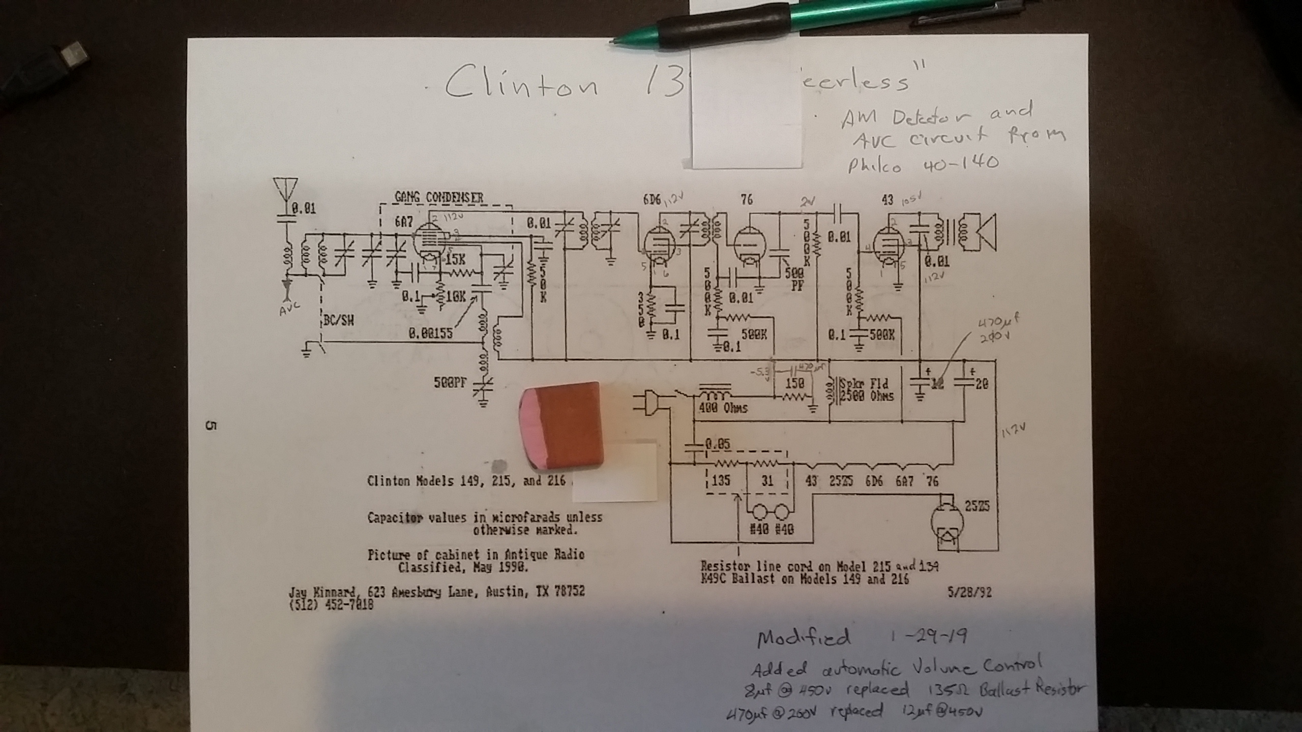
Now here' are the mods. The the detector, the ballast resistor, and the filter cap.
The detector circuit is from a Philco 40-140 with AVC. I cheated and used germanium diodes and reused the 76 tube as a just audio preamp. So the AVC works fair. I attached to where the ground was for the first antenna coil is. It only varies the first RF stage gain. I also added a filter cap to the bias voltage for the 76 tube.
I know I used too big a filter cap at the rectifier. So I am thinking I will add series resistor with the large cap. This should lower the peak rectifier current and still keep the ripple hum down.
And last is the ballast resistor. I replaced it with an 8uf motor run cap. It took a few tries to find just the right value. I measured the filiment voltage of the 25Z5 tube for this. It takes a little longer to warm up but it works with no resistor heat.
I made these mods some time ago. And still need to add the series resistor to the rectifier cap. I will try and post the results.
!!!!!!!!!!!!!!!!!!!RESISTANCE IS FUTILE!!!!!!!!!!!!!!!!!!!!!!
/\/\/\/\/\/\/\/\/\
[Image:
http://philcoradio.com/phorum/images/smi...on_eek.gif] Chris


![[-] [-]](https://philcoradio.com/phorum/images/bootbb/collapse.png)


