Posts: 3
Threads: 1
Joined: Sep 2023
City: Yulee
State, Province, Country: Florida
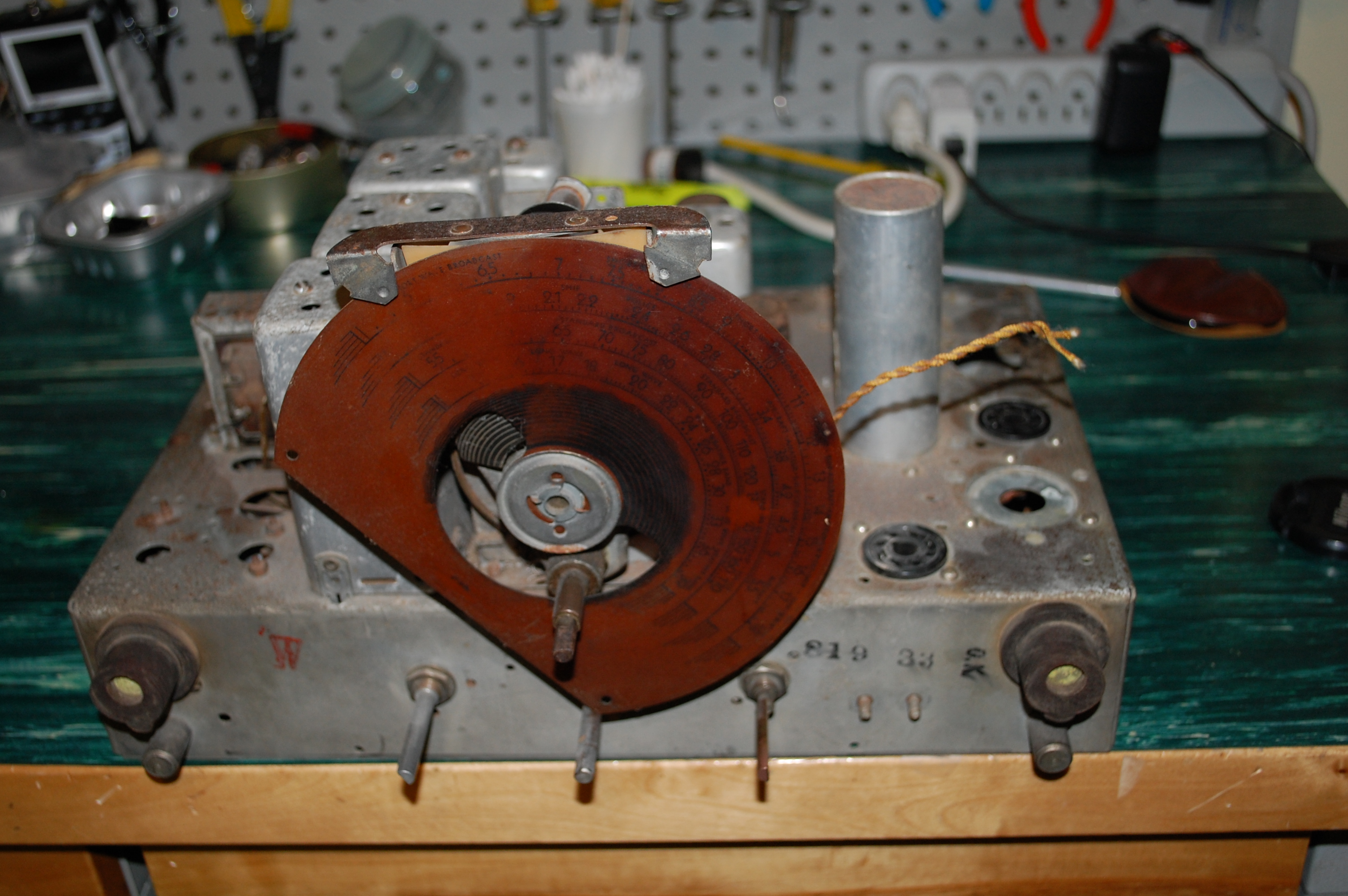
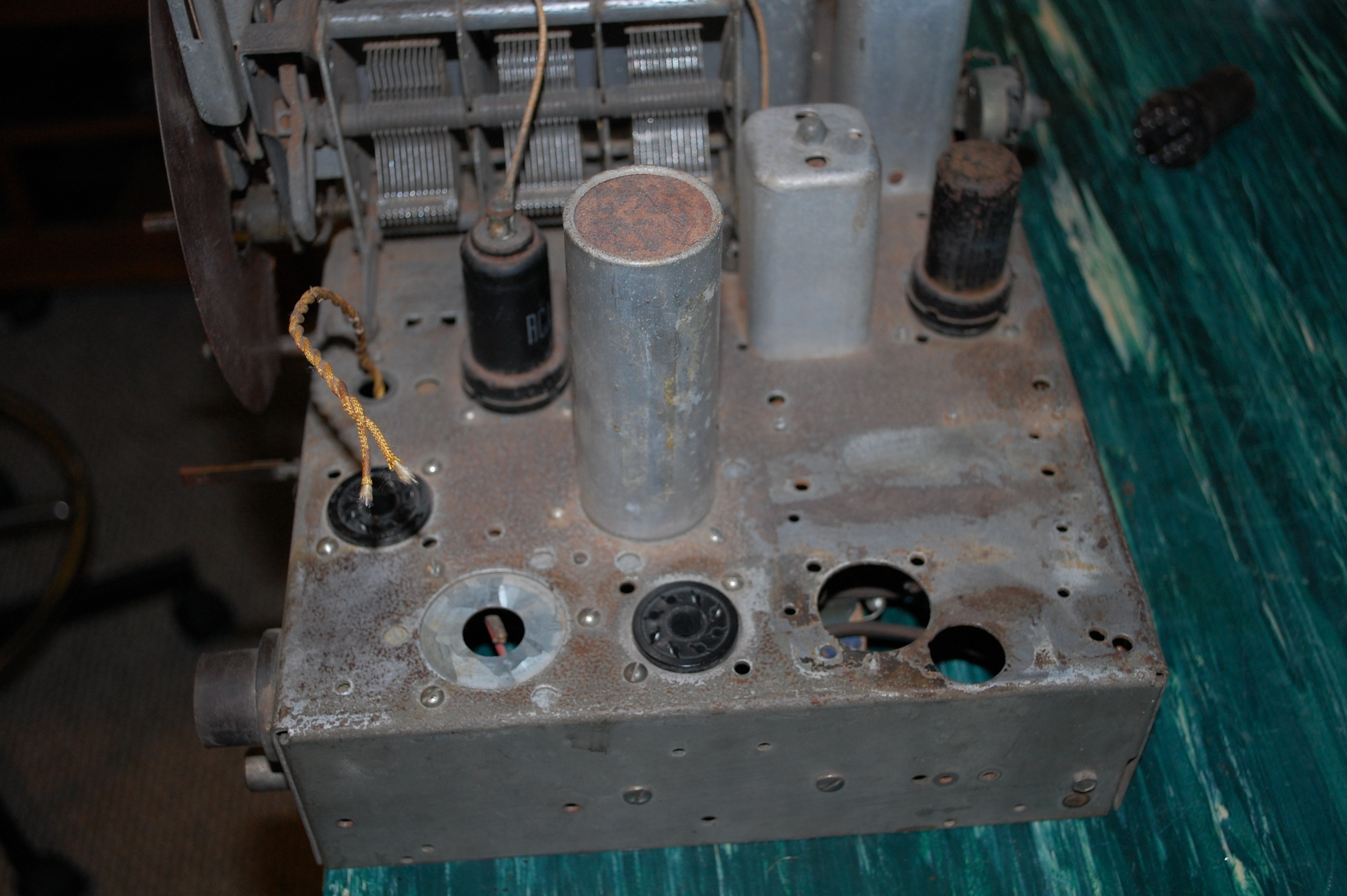
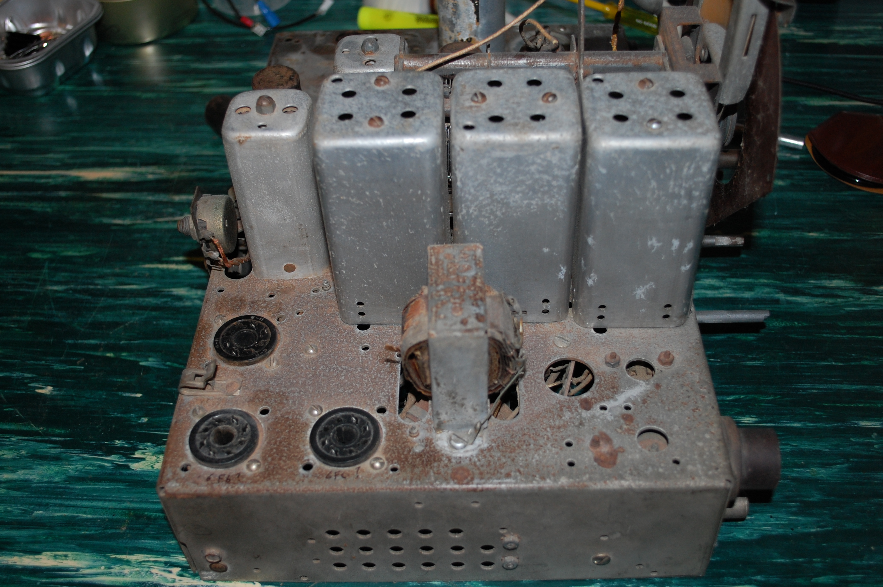
I have a Philco chassis marked 38-1525 that I am trying to identify. It came in a tombstone cabinet marked 38-643. The chassis has simular rf coils and tuning mechanism to a 655 but has all metal octal tubes. It also has two phone Jack's on the back of the chassis for audio input. The wiring is original so I doubt that it was upgraded with more modern tubes or belongs in this cabinet. The power transformer is toast but the rest may come around. Does anyone have any info on this chassis? Any help would be greatly appreciated. Thanks
Posts: 98
Threads: 34
Joined: Feb 2012
City: Philadelphia
State, Province, Country: PA
Thread moved to Philco Home Radio by admin
Posts: 13,776
Threads: 580
Joined: Sep 2005
City: Ferdinand
State, Province, Country: Indiana
Hi,
There is no such thing as a model 38-1525. This may be a Philco part number for some component?
Photos of the chassis would be very helpful. As these left the factory, they were made so only ST (taper-top) glass tubes could be used. It was common for repair shops to modify the tube shield bases (or remove them entirely) so metal or GT tubes could be used. Perhaps this is what happened to your chassis. An audio jack, or jacks, was also a common add-on, not done at the factory but later on by repair shops (and, sometimes, owners themselves).
How many tubes does this chassis have in it? Again - photos would help a great deal.
If you need guidance on posting photos here, please read:
https://philcoradio.com/phorum/showthread.php?tid=29
https://philcoradio.com/phorum/showthread.php?tid=4407
--
Ron Ramirez
Ferdinand IN
Posts: 2,135
Threads: 158
Joined: Jan 2013
City: Westland, MI
Welcome to the Phorum! As Ron said, there is no 38-1525 radio. I suspect that number is the actual chassis part number. Several different radios housed a very similar chassis design. Photographs and tube count would help immensely. If there is a power cord on the radio DO NOT plug it in. Some of these similar chassis were battery sets. Take care and BE HEALTHY! Gary
"Don't pity the dead, pity the living, above all, those living without love."
Professor Albus Dumbledore
Gary - Westland Michigan
Posts: 3
Threads: 1
Joined: Sep 2023
City: Yulee
State, Province, Country: Florida
I'll give the picture attachment a try. The wiring on this chassis looks original and factory. The no. 1 pins on all of the tube sockets are grounded
with exception of the rectifier tube which would indicate to me that it was a metal tube set from the beginning. If it was retubed and modified
later, it was a professional job and I would say completely rewired. The output tubes are wired in pushpull and are along the left side of the
chassis. The audio driver transformer is located on the bottom of the chassis. The IF transformers were made by JW Miller, another possible
indication that it was rewired at sometime. It had 8 tubes originally, some were missing. The set included a 5U4 Rectifier, 6K8 Mixer, 6SK7
RF Amp?, 6SG7 IF?, and a 6SR7 det/amp. Looks like the output tubes were 6F6s. Thanks for reading my post.


Posts: 13,776
Threads: 580
Joined: Sep 2005
City: Ferdinand
State, Province, Country: Indiana
Some observations:
1. Philco did not use metal tubes originally. Philco was feuding with RCA throughout the 1930s. RCA was a heavy proponent of metal tubes. For this reason, Philco refused to use them, instead having Sylvania (who made their Philco branded tubes for them) make glass octal tubes with ST or "taper-top" glass envelopes.
2. Radio manufacturers did not attach tube sockets with screws; they used rivets.
3. Philco used phenolic wafer sockets when this chassis was built, not the black bakelite Amphenol sockets.
4. The IF transformers are not original.
5. Philco did not use octal tubes in their 1936 radio models.
I find it very odd that what is obviously a 1936 Philco chassis would be inside a 38-643 cabinet, unless (a) the chassis was stuck inside backwards or in a manner that the control shafts did not protrude through the front panel; or (b) the front panel was redrilled to accommodate these control shafts.
Can you post photos of (A) a top view of the chassis), (B) an underside view of the chassis, and © a photo of the cabinet, please?
I think the chassis is a heavily modified model 640. It has four bands on the dial scale, and shows evidence of once having a vertical mounting power transformer. It is probably not worth restoring - in my opinion.
--
Ron Ramirez
Ferdinand IN
Posts: 330
Threads: 30
Joined: Aug 2017
City: Hay Lakes, Alberta,Canada
So, the 38-643 was a battery set, and so what I think you have is the original chassis converted to electric. Very common to find battery sets done this way, after electricity came to a rural area in the late 30's and 40's. Usually octal sockets were installed and either 6 or 12 volt tubes (12 volts common after the war) were used, and the set was "rebuilt" as a transformerless AC/DC configuration.
I've seen some done very well by radio shops in the day, and others butchered by "the local handyman"
Posts: 3
Threads: 1
Joined: Sep 2023
City: Yulee
State, Province, Country: Florida
Thanks for the reply Brad. I was in error, the cabinet is a model 643 643A according to the paper inside. So everything now makes sense. The tech that modified this one was a pro. It had a power transformer that I removed. It was toast. Because the cabinet is in good condition after refinishing and the new dial I found plus the quality of the wiring, I may yet restore it. My experience includes many boat anchor restorations. This would be my third or fourth appliance radio. Thank you all for your interest and assistance.
Users browsing this thread:
|
|
Recent Posts
|
|
Zenith H725
|
| The PSU filter cap arrived today (thank you USPS!) so I will work on that later.
Meanwhile, I have the dial, speaker...EdHolland — 06:42 PM |
|
Philco 610B oscillator wiring
|
| Thanks Terry. After checking my notes I think I recorded about -10v at the 6A7 G4/control grid. The screen grid (G3 &...Tubester — 05:59 PM |
|
The list of my radio & TV collection!
|
| Magical chords of forgotten melodies, old nostalgic music on an old radio... Saturday night blues on the Mid-Waves on an...RadioSvit — 12:20 PM |
|
Philco 42-345 Restoration/Repair
|
| Thank you MrFixr55 the issue with this radio is that the internal coil antenna is missing and there was a wire in its pl...osanders0311 — 11:34 AM |
|
Philco 610B oscillator wiring
|
| Regarding the oscillator circuit which is comprised of the 6A7's cathode, control grid, and screen grid. These elements ...Radioroslyn — 10:33 AM |
|
Philco 42-345 Restoration/Repair
|
| Hi OSanders,
First off, welcome to the Philco Phorum where Phine Phamily-Phriendly Pholks Phull of Philco Phacts and P...MrFixr55 — 08:41 AM |
|
Philco 42-345 Restoration/Repair
|
| Today I've been reading through the site trying to learn more about this radio. I also soldered the lose power cord cabl...osanders0311 — 08:24 PM |
|
Philco 610B oscillator wiring
|
| Thanks David! I do have that same later prodution model 610 schematic. I've also studied the Philco service bulletins fo...Tubester — 08:12 PM |
|
Philco 610B oscillator wiring
|
| Some info from Beitmans says late production. David David — 06:06 PM |
|
Restoring Philco 96
|
| Oh wow! Just found this thread. Brings me back to early days on this phorum. I did a 96 back in 2017. Thread here:
...rfeenstra — 06:05 PM |
|
Who's Online
|
There are currently 2446 online users. [Complete List]
» 2 Member(s) | 2444 Guest(s)
|
|
|

|
 
|


![[-] [-]](https://philcoradio.com/phorum/images/bootbb/collapse.png)


