42-327 heater circuit confusion
Posts: 20
Threads: 2
Joined: Oct 2025
City: Springfield
State, Province, Country: Missouri
Ok so I powered up this radio without a connected antenna and on broadcast I have reception with a clear signal. Yay!
A lot of noise dialing across the band but a good cleaning of more dust might help that. Not much on SW more hum, but one very faint station with the antenna.
(This post was last modified: 01-26-2026, 04:29 PM by SlidesK.)
Posts: 20
Threads: 2
Joined: Oct 2025
City: Springfield
State, Province, Country: Missouri
The radio plays good and broadcast and shortwave stations came through, but the line voltage is still high. I tried to wire the heater circuit with the lamp wired to 7c6 as shown in the schematic but it burned up the tube so I’m back to the beginning where I’m confused about the lamp wiring into the heater string. I have a 7b6 and it worked for a quick test for reception and that checked ok. It won’t do for regular use though. I’ve ordered another tube but could really use more help in the wiring. I know the circuit as I’ve wired it pretty well and can draw my wiring but am still confused and continue tracing. The resistors that are out of specs are 1/2 watt so I can’t replace them today. Aside from the resistors being replaced I’m wondering if the heater wiring could be causing the higher B+ and that’s how I burned the 7c6 tube. Trouble reading the way the lamp drops in between 50L6 and 7C6 which are pins 2 and 8. Any suggestions?
Posts: 18,427
Threads: 622
Joined: Oct 2011
City: Jackson
State, Province, Country: NJ
OK.
1. I suggest you do not change the wiring of the filaments, especially considering you do not fully understand what is happening. Lest you be buying more tubes.
2. There was a suggestion you draw the exact wiring of the filaments.
3. By the "Line voltage high" do you mean you have 125VAC and not 115VAC? If yes, go to #4
4. Once you reinstate the wiring that worked, put out the drawing. My suggestion is, use a capacitor in series with the filaments. The capacitor will drop the extra voltage WITHOUT dissipating extra power.
If you put out the accurate drawing, AND provide the accurate AC voltage as measured in your outlet, I will calculate the capacitance for you. Warning: no, simply using a capacitor for the same value of it capacitive impedance that would be equal to a resistance required won't work: there is a phase shift.
People who do not drink, do not smoke, do not eat red meat will one day feel really stupid lying there and dying from nothing.
Posts: 20
Threads: 2
Joined: Oct 2025
City: Springfield
State, Province, Country: Missouri
Hi morph, by line voltage I meant B+ the input is 117v AC and the B+ was measuring 122v down from 130v after replacing a missing wire that I took out due to crumbling. That put a 10k back into the 1st AF/ Det circuit diode plate. Now it’s wired as it was before I tried to put the lamp in at pin 8 of 7C6 which burned the filament. I then put in a 7B6 for a quick check. Checking now B+ is 122vdc on one side of the field, the output side and 95vdc on the rect cathode side. Should be 108 and 83 vdc
The 7B6 is very temporary and reads 81vdc at the plate which should be 28vdc with the 7C6 which I have ordered and won’t receive for a few days. I have studied electronics with a BS in Engineering Physics/ Electronics. Radio tube theory is still a new study to me so I’m stumbling through since I’ve been away from electronics theory and application for almost 20 years. It’s coming back but appreciate all the help I can get.
(This post was last modified: 01-27-2026, 11:11 AM by SlidesK.)
Posts: 18,427
Threads: 622
Joined: Oct 2011
City: Jackson
State, Province, Country: NJ
OK then I would not touch it. Your B+ is OK.
keep in mind, these voltages were measured with 1000 Ohms per volt voltmeter. Which means, if you measure it at, say, 200V range, you'd load your circuit with 200K resistor. Which is an extra load. And you are probably using a DMM.
The difference between the ends of the Field coil is still more or less the same. So leave it be.
If you are so inclined, do an experiment: take a 150K-200K resistor and put it right across your B+ when measuring it (be careful not to get shocked).
See if that changes that voltage.
People who do not drink, do not smoke, do not eat red meat will one day feel really stupid lying there and dying from nothing.
Posts: 20
Threads: 2
Joined: Oct 2025
City: Springfield
State, Province, Country: Missouri
Ok it was playing well with the 7C6 and I do have a Simpson analog meter with a higher resistance too. I’ll wait for the new tube before playing it much. Have a lot
Of cleaning to do on the cabinet and chassis. Thanks for your interest. Thanks for your help.
Posts: 20
Threads: 2
Joined: Oct 2025
City: Springfield
State, Province, Country: Missouri
Just wanted to post an update since the last post. I received the replacement 7C6 tube yesterday and put it in to test today. I dropped the voltage a little since it was running high and I can honestly say that it sounds great. My only concern is a grid bias for the XXD tube for 47k is missing. No note that is was used in code 121 only so I’ll probably put one in and see how it does. Like I said earlier, the voltages are a little high and that’s most everywhere I’ve checked earlier. Just going to check them again and go from there. Thanks for all the help.
Posts: 20
Threads: 2
Joined: Oct 2025
City: Springfield
State, Province, Country: Missouri
Just a quick update on the 42-327 122 radio. It’s all rewired, couple of sockets replaced and it plays really well. The voltages are a little high, but not too bad. The only concern to figure out is the 1AF/ detector tube has a plate voltage that is just at 20v high, but no distortion. SW is good and will get tested after dark. Thanks for all the helpful comments and now I get out the ‘45 ARRL handbook to study more vacuum tube theory.
Posts: 2,327
Threads: 23
Joined: Jul 2020
City: Greenlawn
State, Province, Country: NY
Hi SlidesK,
+1 on what Morzh said.
Please note that on the Code 122 version of this set, that there is no indicator bulb tap on a 35Z3, which is your rectifier. Please note that your set uses a 120V indicator lamp. Best place to put it is between the unswitched leg of the power supply (pins 1 and 2 of the 35Z3) and the "load side" of the switch (B-, negative leads of electrolytic caps, a filament pin of the XXD, etc.). In other words, the indicator lamp is NOT part f the filament string. The original was likely a 3 Watt or 7 Watt indicator light with a base similar to that used in nightlights, old school Christmas lights and chandeliers.
Refer to the drawing attached and my horribly drawn indicator lamp. This is the same diagram that I sent to you to troubleshoot the filament wiring. to cut down on heat, you can use an LED version of a C7 bulb. Note that on the published version of the schematic, the dotted lines indicate the indicator lamp for the Code 122 version. The Xs indicate to the Tech to ignore what is between the Xs. Unfortunately, this made the diagram both difficult to read and incorrect (not showing where a 35Z3 filament goes to instead of the 35Z5 filament.
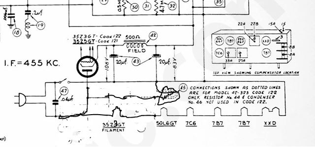
As far as the plate voltage of the 7C6 1st AF stage, verify the resistance of the 470 KOhm resistor and that the 0.01 uF cap is new and good. If this is so, then don't worry. The slightly high B+ voltage will not cause the proportionally much higher B+ on the 1st audio stage.
As to the missing 47K resistor, if it is missing, I don't know if I would worry too much about it. Seems to me that this is the oscillator circuit (The mixer is the right side of the tube), and a 47K resistor is rather low to use as a "grid leak". I would measure between the cathode and grid or between the grid and the negative terminal of the filter caps. If you have a resistance there that is less than 1 MOhm, I wouldn't worry about it. The circuit works.
Hope this helps.
"Do Justly, love Mercy and walk humbly with your God"- Micah 6:8
"Let us begin to do good"- St. Francis
Best Regards,
MrFixr55
Posts: 20
Threads: 2
Joined: Oct 2025
City: Springfield
State, Province, Country: Missouri
Thanks MrFixr, I have the lamp wired like the diagram from before and am using a 4w 120 v bulb. I put the 47k resistor in to check the voltage differences and the 470k resistors had one reading 700+ that was changed when the wiring was being replaced. It's playing very clear and has a good sound. The dial is a little off, not sure if I will change the alignment but will check it. Thanks for the tips, Philco is a new challenge for me.
(This post was last modified: 02-05-2026, 11:16 AM by SlidesK.)
Users browsing this thread: 1 Guest(s)
|
|
Recent Posts
|
|
Philco P45-6365 Universal Transformer Instruction Manual
|
| Can anyone guide me to where this may be found?GRG — 03:00 PM |
|
54C Complete Teardown/Rebuild
|
| I don't think that I have encountered a 12Z3 before, curious how it uses one of those but includes a #43, which is a 25 ...Arran — 02:17 PM |
|
HiFi (Chifi) tube amp build - but my own design.
|
| It's the other forum. I'm also in DIY, but mostly read there. Honestly, I kinda jumped into this without much thought to...TV MAN — 10:43 AM |
|
Philco 71 Code 125
|
| Hello,
I am in need of a schematic for this radio. Mine has the three separate circular tube shields and a shadow me...dconant — 08:06 AM |
|
Stromberg Carlson 1500 Squeal
|
| And life just keeps getting more complicated.dconant — 07:57 AM |
|
54C Complete Teardown/Rebuild
|
| Hello Roy,
here is this one
sincerely Richardradiorich — 12:45 AM |
|
54C Complete Teardown/Rebuild
|
| Richard,
Had grabbed it already but thank you just the same. I find myself wanting to find some way to block out the...glyphmon — 12:03 AM |
|
54C Complete Teardown/Rebuild
|
| Hello roy,
here is a link to the schematic .
Sincerely Richardradiorich — 11:54 PM |
|
54C Complete Teardown/Rebuild
|
| Richard,
The Silvertone 2014 also is a transformerless set, so I am incorporating a 1:1 600 ohm audio isolation transfo...glyphmon — 11:37 PM |
|
Preliminary work on wife's Silvertone 2014
|
| Did an alignment today which was interesting. IF alignment went great, almost all was already spot-on. Adjusting on th...glyphmon — 11:35 PM |
|
Who's Online
|
There are currently 2624 online users. [Complete List]
» 2 Member(s) | 2622 Guest(s)
|
|
|

|
 
|








