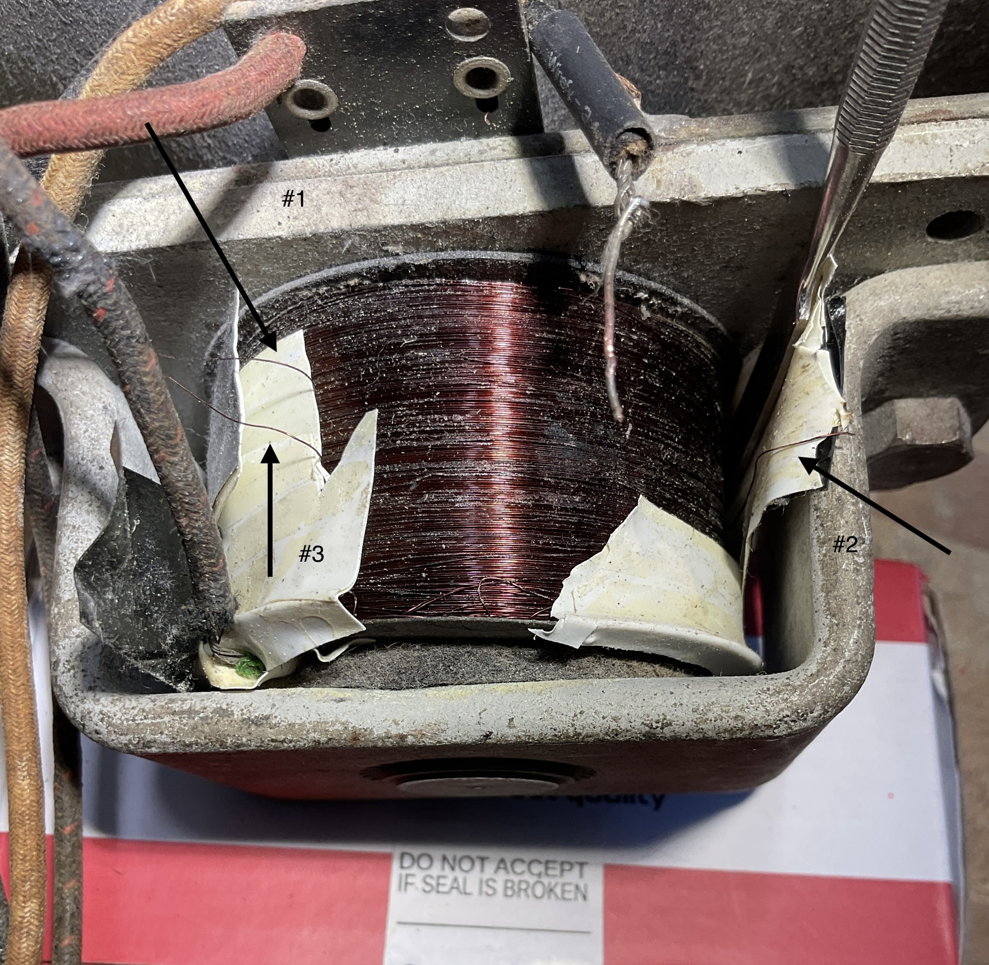
This speaker worked before but when I plugged in this morning I saw a puff of smoke. Immediately unplugged it then took the tape off carefully, noticed a slight burn mark, and found three loose small wires marked 1, 2 and 3 on the pic.
The larger wire in the middle with the piece of heat shrink is where the correct wire needs to be attached. I get continuity between wires 1 and 2. Does that mean that I should solder them together and attach #3 to the larger wire with the heat shrink. I’ve never worked on a speaker field coil before.
Or should I just remove all the tape from surrounding the rest of the field coil and then try to determine where these wires go?
I do have some #38 wire but never used it before. What is the best way to solder these wires together?
Hamilton Wrote: I get continuity between wires 1 and 2. Does that mean that I should solder them together and attach #3 to the larger wire with the heat shrink.
Which brand and model is this radio? It is always wise to specify the brand and model so that we can look at the service information for that set. Many of us have service info for most brands in Rider and Beitman. Some of us also have a number of factory service manuals for non-Philco radios (I have most of the factory service manuals for Zenith and RCA).
I suspect that you don't have a sufficiently sensitive ohmmeter to measure the resistance between wires 1 and 2, and don't have the instrumentation to measure the impedance between them. There are undoubtedly some turns between them, because it would be redundant and unneededly expensive to bring two leads out of the field coil if they were shorted internally.
I agree with Dale, we need to know the make and model of the radio in question. I have a question though, what is that knot I see at the bottom edge of the coil in your picture?
(This post was last modified: 09-20-2026, 11:02 AM by Jim Dutridge.)
If you have continuity between wires 1 and 2 don't tie them together. check to see if you have continuity between either 1 or 2 and the black wire and wire 3. if 3 and the black wire have continuity, and based on the location, I believe that 2 and 3 should be tied together and 1 connects to the heavier lead wire.
Leave slack, consider getting some red GLPT insulating varnish and dribble it over the area of the coil that is exposed from taking the tape off. I expect that you may have some bare wire from the arcing and smoke that you saw. Have a layer of insulation between the coil and all splices.
Hope this helps.
"Do Justly, love Mercy and walk humbly with your God"- Micah 6:8
"Let us begin to do good"- St. Francis
Sorry for the delay in responding but health issues always seem to creep up when you’re my age.
I did get the field coil repaired. I had to unravel about 10 loops because of bare wire but it’s good now. Thanks to all.
It’s a Stromberg Carlson 60L and I have disconnected Part #24189 to totally replace all those caps.
I need some assistance with C-15 and C-5. I can’t tell from the enclosed photo of this capacitor box if these two caps are joined. Also I am assuming that C-15 is two .3 caps.
This is a really nice looking console radio and I would love to get it working again.
I believe I can answer your question about C5 and C15. Look at the apparent connection point and follow the wire up and out of the block where it attaches to a ground lug. Now look at the schematic and locate both capacitors. You'll notice that they are each connected at one end to ground. There might be a ground buss running through the block that connects to the ground lug. You'll also notice on the schematic the value of C15 is 0.6mfd or two 0.3mfd in parallel.
(This post was last modified: 09-27-2026, 09:00 PM by RodB.)
Thanks Rod. Much appreciated. The tar didn’t come out as neatly as I would have liked and two of the tiny wires weren’t connected but I believe I have it figured out.
One thing about the field coil speaker on this set, the rear bracket is bolted in place so you can easily remove it to repair, or rewind the field coil. You just unbolt the bracket, and the bobbin with the field coil should slide right off without disturbing the voice coil, cone, spider, or anything else. Stromberg Carlson used to manufacture their own speakers, so they tended to build them a little better theme with better quality materials, which is more then I can say about the plastic knobs they used.
Regards
Arran