Posts: 825
Threads: 113
Joined: Aug 2012
City: The Villages
State, Province, Country: Florida
Just when I'm begining to think I know what I'm doing I get a new project to remind me that I don't!
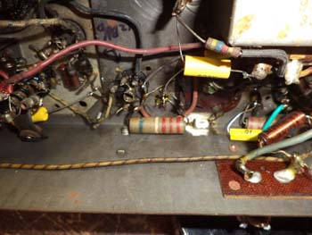
Can someone please tell me what this is? I think it is a capacitor of some kind.
Thanks,
Eric

Eric
The Villages, FL
Member: Philco Phorum, ARF, ARCI & Radiomuseum.org
Posts: 16,533
Threads: 573
Joined: Oct 2011
City: Jackson
State, Province, Country: NJ
Eric
Which one is it? The cylindrical thingy at the bottom with the green/white/three red stripes?
Strange marking for a cap, could be a resistor, but: do you know what radio you are dealing with and do you have its schematic? That would take the guesswork out.
Posts: 825
Threads: 113
Joined: Aug 2012
City: The Villages
State, Province, Country: Florida
Hi Morzh,
Yes, that is the one I'm talking about. It goes from pin 6 of one of the 12AU6s to ground. From looking at the schematic it shows a .003 cap. I tested it and my capacitor tester isn't even close to that value.
Eric
Here's the schematic:
http://www.nostalgiaair.org/Resources/312/M0025312.htm
Eric
The Villages, FL
Member: Philco Phorum, ARF, ARCI & Radiomuseum.org
Posts: 16,533
Threads: 573
Joined: Oct 2011
City: Jackson
State, Province, Country: NJ
Actually it shows 0.01uF cap, but still does not fit the marking.
Posts: 825
Threads: 113
Joined: Aug 2012
City: The Villages
State, Province, Country: Florida
What does the marking say? Is it a cap?
Eric
The Villages, FL
Member: Philco Phorum, ARF, ARCI & Radiomuseum.org
Posts: 16,533
Threads: 573
Joined: Oct 2011
City: Jackson
State, Province, Country: NJ
Not sure....red is 2, white is 9, green is 5.
Posts: 825
Threads: 113
Joined: Aug 2012
City: The Villages
State, Province, Country: Florida
Are the color codes the same for resistors and caps? Is this a cap?
Eric
The Villages, FL
Member: Philco Phorum, ARF, ARCI & Radiomuseum.org
Posts: 1,114
Threads: 14
Joined: Feb 2013
City: Irvington, NY
The cap connected to pin 6 of the 12AU6 ( 12BA6?) looks like it is C13, a screen bypass cap. It appears from the color code to be 2200 pF, (.0022 uF), which puts it pretty close to the .002 uF I read on the schematic for C13.
What did you measure the mystery cap's value to be? It definitely looks like an early molded paper cap, with the resistor color code used for indicating value.
Edit: I looked at the photo again and it looks like the mystery cap is connected to pin 6 of the 12BA6 first IF tube. It appears that the second IF 12BA6 also uses the same .002 uF screen bypass. The 12AU6 tube should be the limiter, connected to the discriminator transformer near the 19T8.
(This post was last modified: 04-01-2013, 03:15 PM by
Mondial.)


![[-] [-]](https://philcoradio.com/phorum/images/bootbb/collapse.png)


