40-195/200/201 Speaker Socket
Posts: 348
Threads: 48
Joined: Oct 2013
City: Tioga, Texas, USA
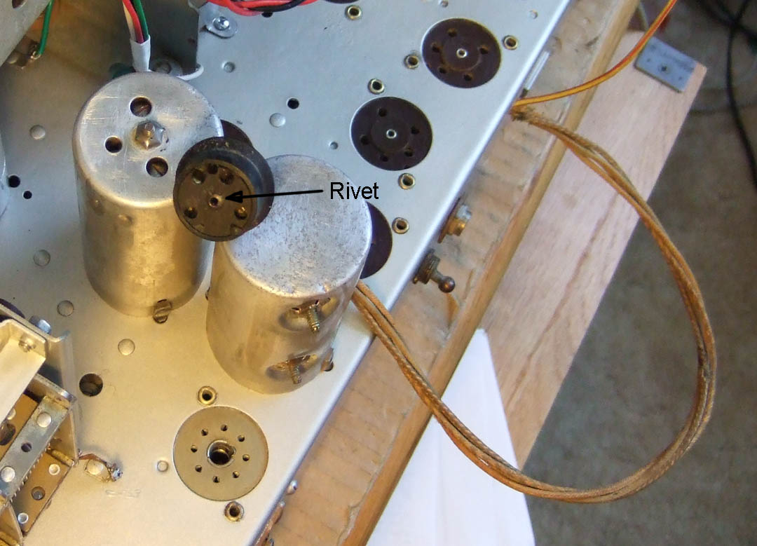
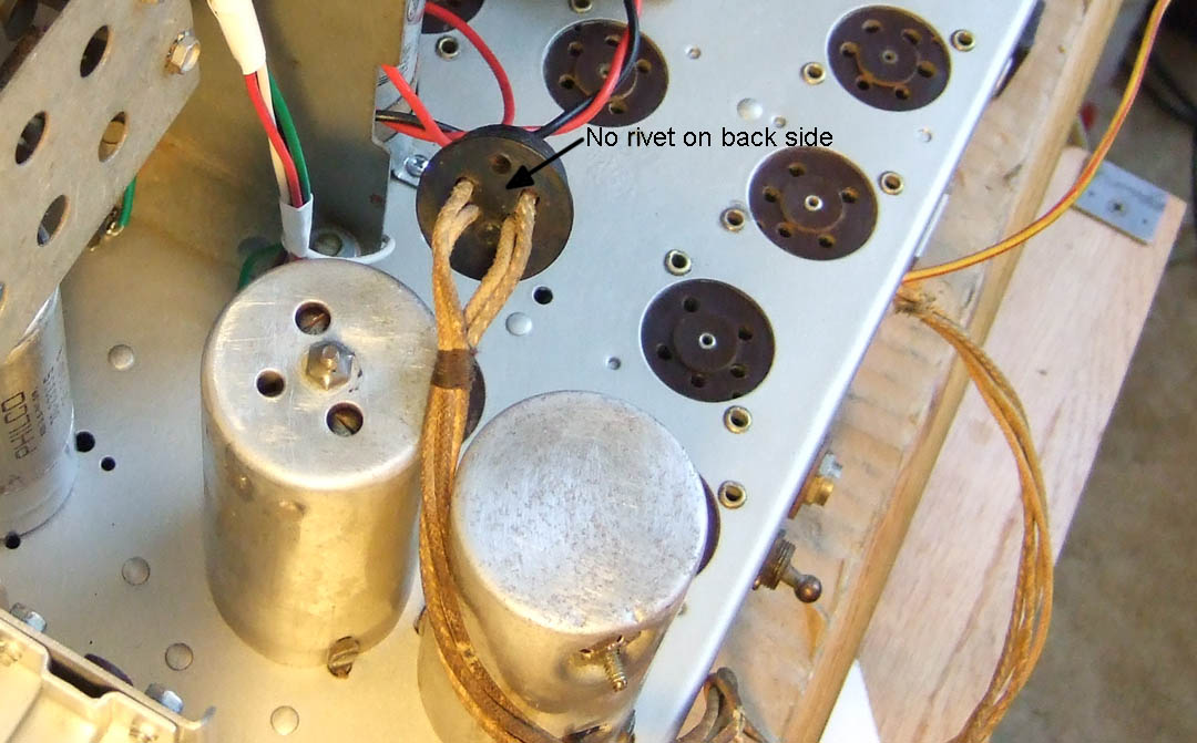
I want to replace the wires going to the speaker socket of my 40-201. Here are a couple of pictures of the socket front and back side. On the front (the side that plugs onto the speaker mounted plug) there is a brass rivet. On the back where the wires enter, there is no rivet at all.


Is it possible to file or drill the rivet head off and remove the fish-paper cover, then solder new wires to the internal contacts, and put the fish-paper cover back on? In other words, can the rivet be removed and a small hole drilled to accept say no. 4-40 hardware to reassemble the socket?
Or, is it possible to do it another way?
Thanks in advance.
Joe
Posts: 2,128
Threads: 18
Joined: Oct 2008
City: Merrick, Long Island, NY
Certainly quite a few alternatives. Any riveit can be carefully and slowly drilled out and replaced afterwoods with a screw and some reinforcement ala bondo or whatever after everything checks out and should be good for another 50 years of so. can't tell exactly, but if the socket is identical to a 5 pin tube, you could harvest a dud carefully and use the base, and even save the old wiring in a little bag for future purists, (I wouldn't but some might bother.) Certainly octal plug/socket sets are pretty easy to come by too, just so long as everything sets up properly, but do keep notes on just what you changed and tuck them into a little piece of plastic wrap stapled or glued to the inside cabinet if you care to.
Posts: 16,560
Threads: 573
Joined: Oct 2011
City: Jackson
State, Province, Country: NJ
If you drill out the rivet DO NOT try to use another rivet as a rivet with a riveting tool - you will crush the case.
If you still want a rivet in there, take a proper size copper or brass rivet, take out the mandrel, and use any large drill with obtuse conical end and a hammer to flare it to hold the case together. Do it gently.
Posts: 348
Threads: 48
Joined: Oct 2013
City: Tioga, Texas, USA
Thanks for the input. I might give the drill-out a try. I should be able to carefully drill the hole all the way through and get a suitable screw and nut through it. There are some even smaller ones than 4-40 if need be. I also have some needle files I bought from Brookstone years ago and a small round file might be just the thing to use if the hole is just a bit too snug for readily available machine screws. I think the screw head would likely be best on the mating side and the nut on the backside.
I think I will keep the original socket because if the speaker ever has to be replaced with a similar field core speaker, it will be best to just be able to plug it in rather than having to change wiring. The OEM wires were cloth covered but were quite brittle and due to all the handling I put the chassis through while removing top-side components, cleaning and painting the insulation on the speaker wires broke open.
I plan to put a plastic sleeve inside the cabinet similar to those that can be placed in loose leaf binders. I will indeed include information on any circuit changes that I may make. I plan to keep things as near to original as I can within economic reason. If I make a change to an alternate wire color (as I have already done in a few cases) I will make a note on a copy of the schematic and include that.
Joe
Posts: 348
Threads: 48
Joined: Oct 2013
City: Tioga, Texas, USA
Morzh;
Yes pop-rivet tools exert far too much force. Even using a machine screw and nut has to be done carefully. You do not get a second chance with many older plastics. It might be possible to repair a cracked case with epoxy, but it is better to not have to do that.
Thanks.
Joe
Posts: 438
Threads: 15
Joined: Jul 2008
City: Anacortes, WA
This might be a good application for a nylon screw and nut combination if you drill all the way through.
Posts: 348
Threads: 48
Joined: Oct 2013
City: Tioga, Texas, USA
Today I managed to locate some 2-56 machine screw hardware and proceeded to drill out the rivet in the speaker receptacle to replace the old fraying wires. I had enough stranded wire on hand to get most of it done except for the speaker minus lead, for which I choose to use a black wire. My Jameco hook-up wire order has not arrived just yet. Once I have it I can complete this part of the chassis rewiring.
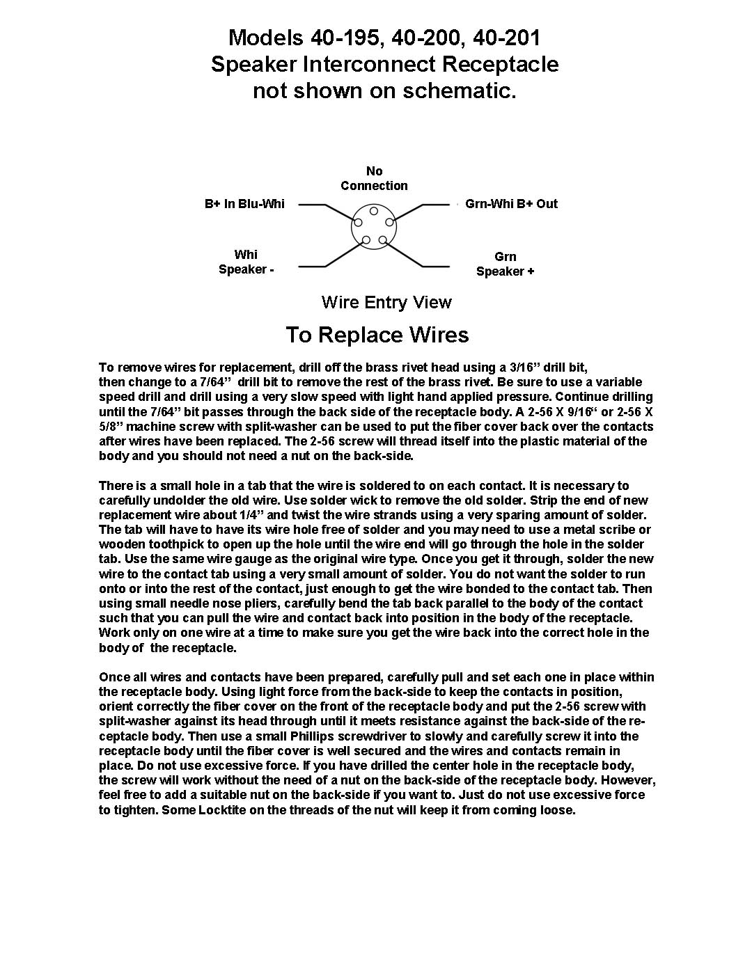
Here is a drawing I made in Photoshop to show the details related to the speaker receptacle. It is not shown on the schematic for the 40-195/200/201 so this may be helpful to others in understanding how the wires connect to/from the field core and the voice coil.
Joe

The above illustration is the wire entry view (back side) of the connector.
(This post was last modified: 12-15-2013, 08:01 AM by Joeztech.)
Posts: 348
Threads: 48
Joined: Oct 2013
City: Tioga, Texas, USA
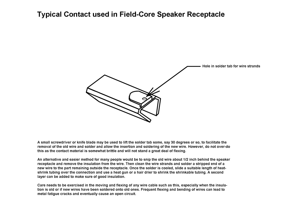
I decided to add an illustration of a typical speaker receptacle contact so it would be easier to understand how the wires are attached to it. Hope this helps others.
Joe

(This post was last modified: 12-13-2013, 03:31 PM by Joeztech.)
Posts: 348
Threads: 48
Joined: Oct 2013
City: Tioga, Texas, USA
jontz;
You sent a query about a *.pdf version of the drawings. Your comment does not show up here and as a result, I do not know how to contact you to send them. If you post a response here I can click on the e-mail tab and get in touch with you.
Joe
Posts: 5,204
Threads: 276
Joined: Nov 2012
City: Wilsonville
State, Province, Country: OR
Joe, his profile also has an email tab, you can see it here:
http://philcoradio.com/phorum/member.php...e&uid=1698
Posts: 348
Threads: 48
Joined: Oct 2013
City: Tioga, Texas, USA
klondike98;
Thanks for that link. I have sent jontz a message. There does not appear to be a way to attach files to the e-mail through the Phorum, so some alternative will have to be found.
An interesting aspect of the speaker receptacle is that looking at the illustration, which is of the wire entry view, the B+ leads are spaced widely apart while the voice coil leads are close together. However, when you look at the mating face, the B+ leads are spaced close together while the voice coil leads are spaced widely apart. It has to do with the way the wire/contact parts are oriented as they are inserted into the body of the receptacle.
Joe
Users browsing this thread:
|
|
Recent Posts
|
|
Philco 46-1209 strange behavior
|
| And no hum without the 7AF7? Not common but I am thinking heater - cathode short. This would introduce hum in this sta...MrFixr55 — 11:14 PM |
|
schematics
|
| Those filter caps in the cardboard tube are easy to restuff, especially the kind with the rolled over end. You don't hav...Arran — 09:56 PM |
|
Philco Model 16 wiring question
|
| If you have 5 wires, do this:
The wires that go to thick-wire wound winding are the filament.
If you do not know wha...morzh — 09:03 PM |
|
Philco Model 16 wiring question
|
|
I recently acquired a Philco Model 16 Code 126. I removed the power transformer to place heat shrink on some very bad...bobclausen — 08:23 PM |
|
1949 Motorola 5A9M
|
| Hello Bob,
That battery looks great nice job !
Sincerely Richardradiorich — 08:20 PM |
|
1949 Motorola 5A9M
|
| Yes, I plan to put a Velcro closer on the top.klondike98 — 07:28 PM |
|
1949 Motorola 5A9M
|
| Nice job on the battery, Bob. Can the box be opened to replace the 9 volters?RodB — 11:32 AM |
|
Philco 46-1209 strange behavior
|
| Thank you for the detailed response MrFixr.
To clarify, the hum starts when the tubes are fully warmed up, and goes a...sq65 — 09:15 AM |
|
Philco 46-1209 strange behavior
|
| MrFixr
The chassis, if there is no ground pin in the AC plug, due to the Y-caps from L/N to the chassis, is at 60VAC re...morzh — 08:47 AM |
|
schematics
|
| thanks I'll try the polar caps seperatelymseno — 07:38 AM |
|
Who's Online
|
There are currently 757 online users. [Complete List]
» 1 Member(s) | 756 Guest(s)
|
|
|

|
 
|


![[-] [-]](https://philcoradio.com/phorum/images/bootbb/collapse.png)


