Posts: 348
Threads: 48
Joined: Oct 2013
City: Tioga, Texas, USA
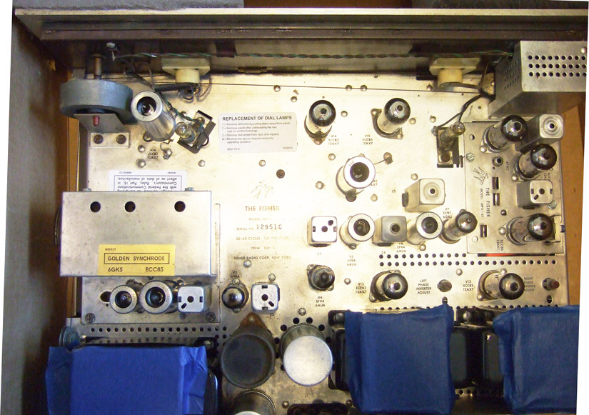
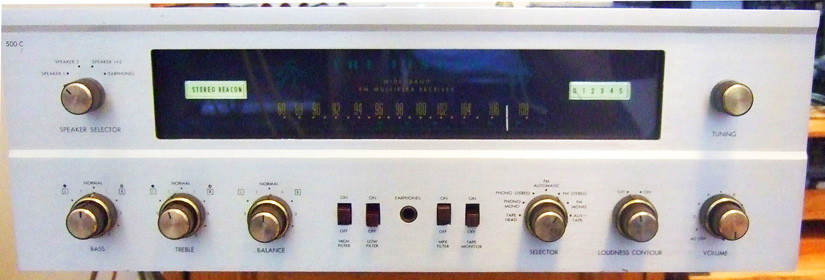
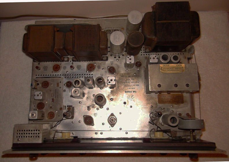
I have been working on restoring a Fisher 500-C model lately. This one is among the earliest ones released, SN 10000-19999 and as such uses 6GK5 RF Amp and 6AQ8/ECC85 Mixer Osc tubes instead of having the Nuvistor front end of the later models. It was missing the dial lamp replacement label. The FCC compliance label and the GOLDEN SYNCHRODE labels were damaged and hard to read. The unit had a lot of rust on the output transformers and cleaning was a real must for this unit. Some of the cleaning wound up removing some lettering on the chassis. I created new lettering using Testor's decal kit and my ink-jet printer. The dial lamp, FCC label and GOLDEN SYNCHRODE labels were reproduced on my laser printer. Gold foil paper for the front end label was found at a hobby shop. Transformer end bells were removed, cleaned and repainted. The chassis cleaning required lots of time and effort.
I just finished cleaning the front glass and meter faces and installed rebuilt festoon lamps for the dial. I am now working on adding Dave Gillespies EFB circuitry to the unit and will also add the Fisher Forum of AudioKarma.org IBAM modification that allows individual output tube bias setting for best life and lowest distortion.
This will be a great performer when finished. See pictures at:
http://s1213.photobucket.com/user/rubal1...t=2&page=1
Joe
(This post was last modified: 10-21-2015, 09:09 AM by
Joeztech.)
Posts: 348
Threads: 48
Joined: Oct 2013
City: Tioga, Texas, USA
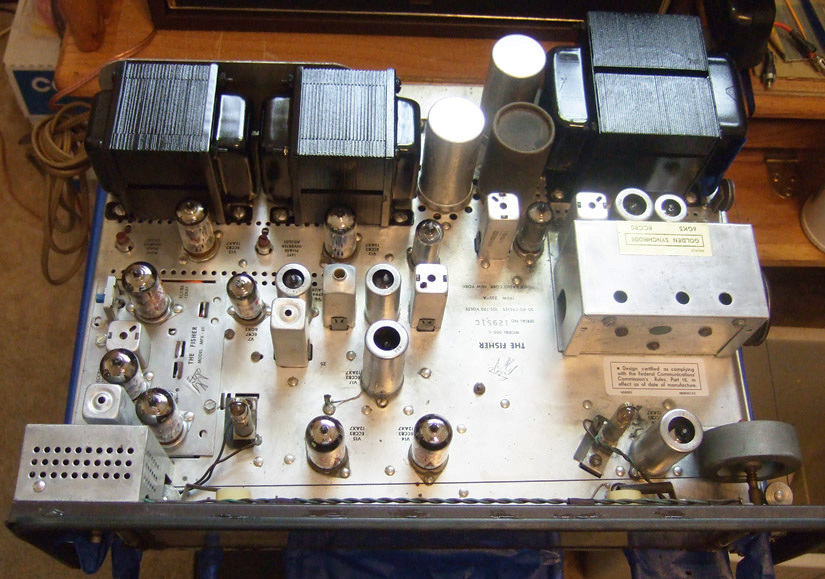
Here is one picture that shows the chassis after the transformers were cleaned and repainted.
Joe
Posts: 348
Threads: 48
Joined: Oct 2013
City: Tioga, Texas, USA
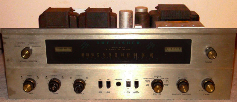
I thought a couple of pictures of the starting point on this one would be useful. The unit was minus all the tubes.
Joe
Posts: 13,776
Threads: 580
Joined: Sep 2005
City: Ferdinand
State, Province, Country: Indiana


Great work!
--
Ron Ramirez
Ferdinand IN
Posts: 348
Threads: 48
Joined: Oct 2013
City: Tioga, Texas, USA
Ron;
Thanks for the compliment.
I really like Fisher equipment and this will be my second one and a real keeper! The most difficult item to clean was the MPX-65 subchassis. Its surface was significantly darker than the rest of the chassis. Someone on the Fisher forum said they were made in West Germany and the date codes for that part were slightly different from the rest on the main chassis. The cleaning on that circuit resulted in complete removal of the nomenclature on it. I recreated them using Testor's clear decal kit. I copied a Fisher bird from a service manual copy I had and entered new text in Adobe Photoshop to duplicate all the text that went on the MPX-65.
While I was at it, I also have duplicated the output tube lettering and the Reverb In/Out graphics on the same decal sheet and will be replacing those too. When I am finished I will put a light coat of Carnuba wax (without any abrasives) to help protect the chassis finish.
Initially the tuning capacitor was stuck and needed lots of lubrication and cleaning of the drive elements and gears. Now it turns much easier and glides along when the tuning knob is turned.
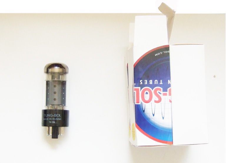
This 500-C will get a new set of Tung-Sol output tubes which are the best new replacements available these days. The IBAM adjustments will help dial them in to 34mA per tube which is their sweet spot. These can produce about 33-34 Watts per channel at low distortion like the original tubes.
Joe
Posts: 2,128
Threads: 18
Joined: Oct 2008
City: Merrick, Long Island, NY
I still remember a stack of 500 C's in the jobber where I interned part time as a kid. The manager looked at 'em and said, "It could be my house!" Congrats on the restoration, should serve you well for a very long time.
Posts: 348
Threads: 48
Joined: Oct 2013
City: Tioga, Texas, USA
Today I finally finished most of the work on the receiver. I installed the new Tung-Sol tubes one by one and adjusted bias as each was installed. There was some interaction between the group of bias controls but I used multi-turn resistors and was able to set tube current to within +/- .001mA and chose to start out at 30mA per tube. That has them running somewhat cool. After some listening time has been put on the unit I plan to increase the current up to 34 to 38mA per tube as indications are from engineers familiar with these tubes say the lowest distortion can be obtained in that range. I have a few residual issues to clear up to be completely finished. The unit has good sound that is full bodied and pleasing to listen to. It has very good selectivity for an older tube type unit. I can pick up a weak station next to a strong local station on an alternate channel frequency and this unit delivers good sound with no bleed-thru from the strong local station.
I bought a new walnut cabinet to put it in after I finish all the minor wrap-up issues. The photobucket site has all the latest pictures there along with the circuit schematic of all modifications.
Joe
Posts: 344
Threads: 38
Joined: Jun 2011
City: Tustin
State, Province, Country: California
Very nice restoration!
I have several Fishers as well including a later 500C. Fisher ran the 7591's to their limit during the "most watts" war back in the early 1960's. As you did, I bias them cooler to last longer. 7591's are not a few dollars like they were when the 500C was made .
Posts: 2,128
Threads: 18
Joined: Oct 2008
City: Merrick, Long Island, NY
Agree, dial down the outputs to make 'em last. You can also repurpose a little quiet fan from a discarded computer power supply to keep things cooler, especially if you are using the stock cabinet.


![[-] [-]](https://philcoradio.com/phorum/images/bootbb/collapse.png)


