38-60 Gonna be a lot of Trouble
Posts: 395
Threads: 33
Joined: Jul 2013
City: Horsham, PA
Hi,
I finally decided to tackle the 38-60 that I've had for a few years. To say the least, it is in rough shape. The speaker cone is pretty much gone, the dial scale is cracked and the top side veneer is completely missing. Those are some of the obvious problems, but yesterday I found another one. Probably not surprising to anyone, but the BC antenna transformer's primary winding is open.
I previously rewound a model 19 oscillator tickler coil. It was relatively straightforward to remove that coil form and then replace the open coil. In this case, I'm not sure how to remove the coil form from the chassis. It is held in place, but I can't figure out how. Does anyone know the correct way to remove this? I don't want to damage the form.
If I can get the coil out, I'm sure I can count the turns, but does anyone know what gauge of wire to use for this? I have a couple of sizes of magnet wire on hand (#32 and #36). Would it be critical to use the correct wire gauge, or can I just use the closest size that I have?
Thanks
Jon
Posts: 7,296
Threads: 268
Joined: Dec 2009
City: Roslyn Pa
So which ant coil? Both the BC and SW?
Long answer is take it apart and rewind. BC coil is going to be about 19' of 38ga wire.
Short answer is parallel #1a w/a 100pf mica cap.
When my pals were reading comic books
I was down in the basement in my dad's
workshop. Perusing his Sam's Photofoacts
Vol 1-50 admiring the old set and trying to
figure out what all those squiggly meant.
Circa 1966
Now I think I've got!
Terry
(This post was last modified: 03-19-2017, 10:19 AM by Radioroslyn.)
Posts: 395
Threads: 33
Joined: Jul 2013
City: Horsham, PA
Hi Terry,
It is just the primary side of the BC antenna xfrmer. The SW ant. xfrmer has no open coils. I guess I'll have to get some 38ga wire.
Really not sure how the coil form fastens to the underside of the chassis. If anyone has thoughts on how to remove the coil form, I'd appreciate their input. Otherwise, I'll keep looking...
Thanks Terry!
Jon
Posts: 7,296
Threads: 268
Joined: Dec 2009
City: Roslyn Pa
Post a pic or two of the top and bottom of the transformer. Most have a couple of screws in the top that secure the coil and the can has a couple of spring fasteners that you squeeze with a pair of needle nose pliers the pop the can off.
When my pals were reading comic books
I was down in the basement in my dad's
workshop. Perusing his Sam's Photofoacts
Vol 1-50 admiring the old set and trying to
figure out what all those squiggly meant.
Circa 1966
Now I think I've got!
Terry
Posts: 395
Threads: 33
Joined: Jul 2013
City: Horsham, PA
Terry,
Here are 3 images.
In the first (38_60_Ant_Coil_1), the BC antenna coil is the lower right coil form of the four. The front of the chassis is toward the top of the image.
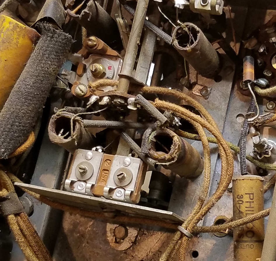
The second image (38_60_Ant_Coil_2) is from the side, the BC coil is in the lower left. The front of the chassis is toward the right side of the image.
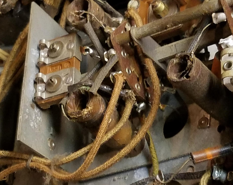
The third image (38_60_top_side) shows the top of the chassis. The BC antenna is to the left of the big cap can, beneath the tuning cap assembly. I don't see any screws underneath the tuning cap.
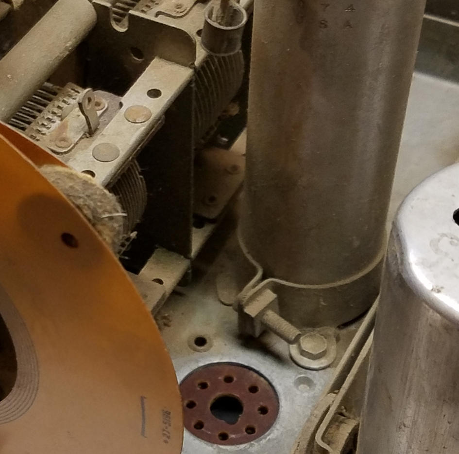
From images 1 and 2, it looks like there is a whole assembly with a right-angled bend that is mounted beneath the chassis. Maybe there is a screw coming from the top side of that?
Jon
Posts: 7,296
Threads: 268
Joined: Dec 2009
City: Roslyn Pa
Not seeing what I was thinking of. I'd put a 100mmfd cap across the top of the pri over to top of the secondary and be done w/it.
When my pals were reading comic books
I was down in the basement in my dad's
workshop. Perusing his Sam's Photofoacts
Vol 1-50 admiring the old set and trying to
figure out what all those squiggly meant.
Circa 1966
Now I think I've got!
Terry
Posts: 670
Threads: 11
Joined: Sep 2014
City: Bellmawr, NJ
looks like it attached to that flooding chassis,,of the tuner,,I see screws to that tuning chassis is separate ,,in Pic 1,,,WOW
Posts: 395
Threads: 33
Joined: Jul 2013
City: Horsham, PA
I looked at it again, it seems like the coil forms attach to a "band switch sub-sub-chassis" which is attached to the RF sub-chassis. Modular design gone haywire 
I guess I'll start by pulling the RF deck and take it from there. Maybe when I get that out I'll be able to see how these coil forms attach. I would prefer to rewind the coil if possible. I'll keep the idea of using a cap to shunt across the windings in my back pocket.
Thanks for all the help Terry, much appreciated!
Jon
Posts: 670
Threads: 11
Joined: Sep 2014
City: Bellmawr, NJ
Happy Trails,,My Friend-----CHEERS
Posts: 395
Threads: 33
Joined: Jul 2013
City: Horsham, PA
Hello again everyone. It has been a slow summer for me radio-wise. I am finally...almost done with this radio.
My question now is this. Does anyone know of a source for the chassis washers that support the RF sub-chassis on a 38-60? One of mine got damaged in removing the sub-chassis from the main chassis. I looked on Radio Daze and didn't see anything that looked quite right.
Thanks in advance.
Jon
Posts: 16,476
Threads: 573
Joined: Oct 2011
City: Jackson
State, Province, Country: NJ
Tried Renovated Radios yet?
People who do not drink, do not smoke, do not eat red meat will one day feel really stupid lying there and dying from nothing.
Posts: 395
Threads: 33
Joined: Jul 2013
City: Horsham, PA
I had not thought of them, but I will give them a look. Thanks for the tip.
Posts: 395
Threads: 33
Joined: Jul 2013
City: Horsham, PA
I finally finished this set a couple of days ago. I needed to:
1) Get the speaker re-coned.
2) Install new veneer on the top. First time for me.
3) Perform some rather significant cabinet repairs, as the cabinet itself and various parts of the veneer were literally coming unglued.
4) Replace the open antenna transformer. I decided to buy a replacement from AES. Seems to work great.
5) Install a new photo finish on the front. First time for me.
6) Recap and re-carbon as usual.
This was probably the most difficult restore I've done so far. At times it really challenged my patience. I actually had to remove the RF sub-chassis twice because of a boneheaded move I made  The mounting bracket for the shortwave antenna coil had broken at some point in the past, so I fashioned a new way to mount it. What I didn't realize until I had it all back together and tried aligning the SW band, was that my mounting bracket actually shorted out the SW antenna coil. I never even looked to see if that might be happening! In order to undo what I had done, I had to take it ALL...BACK...APART...ugggghhhh!!!
Thankfully, that is all in my rear view mirror now and overall, I am happy with the result. It receives great on both bands. Here are a couple of photos
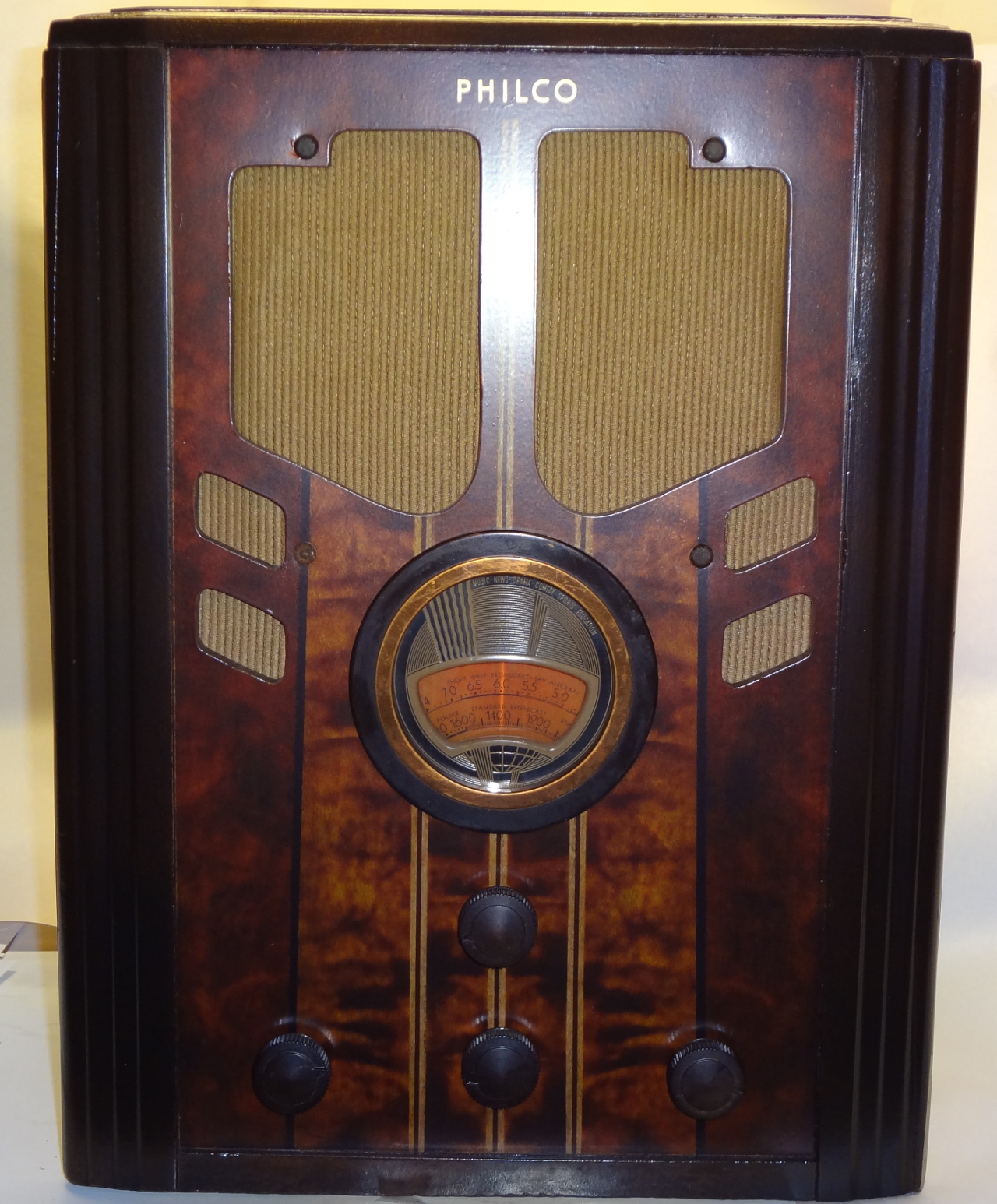
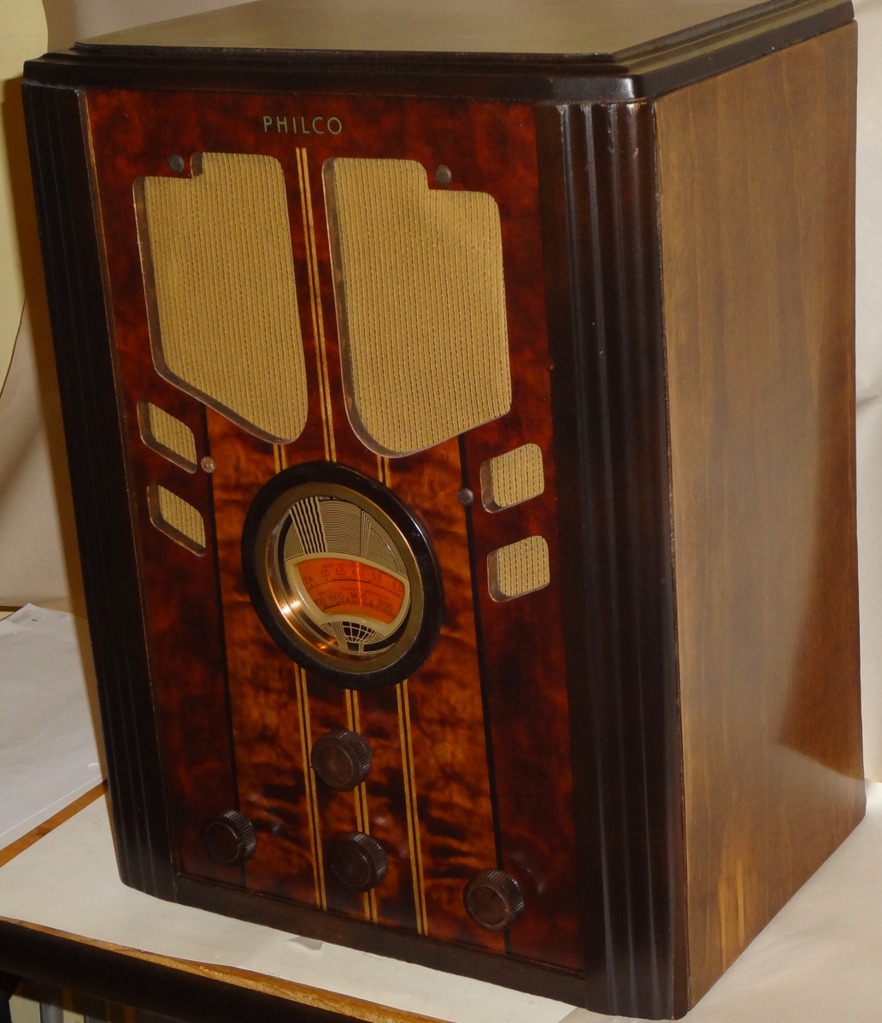
A big thank you for everyone's input throughout.
Jon
Posts: 203
Threads: 20
Joined: Feb 2017
City: Orland Park
State, Province, Country: Illiinois
Nice!
Greg
"We are here to laugh at the odds and live our lives so well that Death will tremble to take us."
Posts: 16,476
Threads: 573
Joined: Oct 2011
City: Jackson
State, Province, Country: NJ
Looks really nice.
People who do not drink, do not smoke, do not eat red meat will one day feel really stupid lying there and dying from nothing.
Users browsing this thread:
|
|
Recent Posts
|
|
Philco 610B oscillator wiring
|
| > The cathode as noted is wired directly to the ground side of the heater filament for that tube, not to the #17 and ...Radioroslyn — 08:12 PM |
|
HiFi (Chifi) tube amp build - but my own design.
|
| Tim;
I noticed your post a little late, but I would take one of the junk sockets and try to break a chunk out of it wi...Arran — 08:07 PM |
|
Need to purchase some accessories for restoration of my Old Philco Radio
|
| Here is a list of resources found in our online library that you might find useful. Mike's Gobs of Knobs email addres...klondike98 — 01:46 PM |
|
First Radio restoration
|
| Hi Tubeman,
Welcome to the Philco Phorum. Phamily Phriendly Pfun with Phine Pholks Phull of Philco Phacts. (See a p...MrFixr55 — 12:33 PM |
|
First Radio restoration
|
| You could post in the WANTED ADs section here on the Phorum and see if anyone has an RF generator that they want to sell...klondike98 — 11:55 AM |
|
Zenith H725
|
| Good ideas, thank you Arrange and Rich. I have the adhesive aluminum foil already and can try that immediately.
More ...EdHolland — 10:18 AM |
|
Graphics for majestic 1050 dial glass.
|
| Murf;
I found this thread on the ARF, the first photo has a pretty good view of the dial glass.
Regards
ArranArran — 01:12 AM |
|
Zenith H725
|
| hello Ed,
how about that speacial tape used for ducting it's like foil or how about thin piece of
aluminum roof flash...radiorich — 12:19 AM |
|
Zenith H725
|
| Ed;
One material that I have seen, but never tried for this was material for making exhaust gaskets, it's similar to ...Arran — 11:42 PM |
|
Zenith H725
|
| I just remembered, I have some hi temp silicone rubber material which could do the trick. Or a piece of FR4 laminate. Th...EdHolland — 08:39 PM |
|
Who's Online
|
There are currently 1590 online users. [Complete List]
» 1 Member(s) | 1589 Guest(s)
|
|
|

|
 
|


![[-] [-]](https://philcoradio.com/phorum/images/bootbb/collapse.png)


