01-15-2022, 12:22 AM
Success! This thread lapsed for a bit as Terry and I were PM'ing back and forth, but today I finally finished the radio and it actually plays clear and strong! I could not have done it without Terry's help, guidance and expertise. He has the patience of a saint and the knowledge of a scholar and we are so fortunate to have him on the Phorum. My hat is off to you, my friend!
For those following along, on his original Power Supply design, the only changes made were:
The IN4007 diode was replaced with a Full Wave Bridge Rectifier for the HV
TWO IN4004 diodes for the Filament side were used in parallel to get 3A out of them.
The LM317T Adjustable Voltage Regulator was replaced with a LM317K, along with the heat sink that was designed for it, and heat sink paste to dissipate the heat. VERY important as it gets very hot otherwise. It's rated for 1.5A and the radio itself is 1.35A so it's getting close to it's limit.
I used a 10K mfd @ 50v e-cap instead of the 5K mfd , 20v that Terry specified, as I had one on hand.
For the voltage divider resistors, I used a 50 ohm on top, and a 10K ohm on the bottom, which calculated to 139v output.
It's also VERY important to have a good ground and keep the leads as short as possible. I had a terrible garbled sound problem that was all related to my having everything just "gator" wired together prior to mounting it in the enclosure. Once everything was properly soldered, it plays nice and clear.
In an unrelated problem, the bias cell batteries were naturally dead, so I tried dropping them in boiling water to recharge them. It kinda worked, but I was only getting .8 volts out of them. So I made a copper plug for the cups and a surround to isolate the sides of the battery (which are positive) from the sides of the cup and replaced all of them with #13 hearing aid batteries. Those are 1.45 volts, more what the original ones should have been.
So here are some pics of the power supply in process:
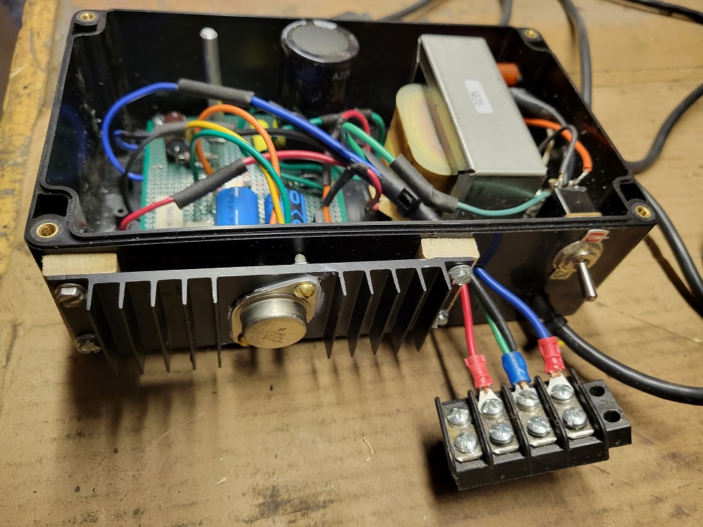
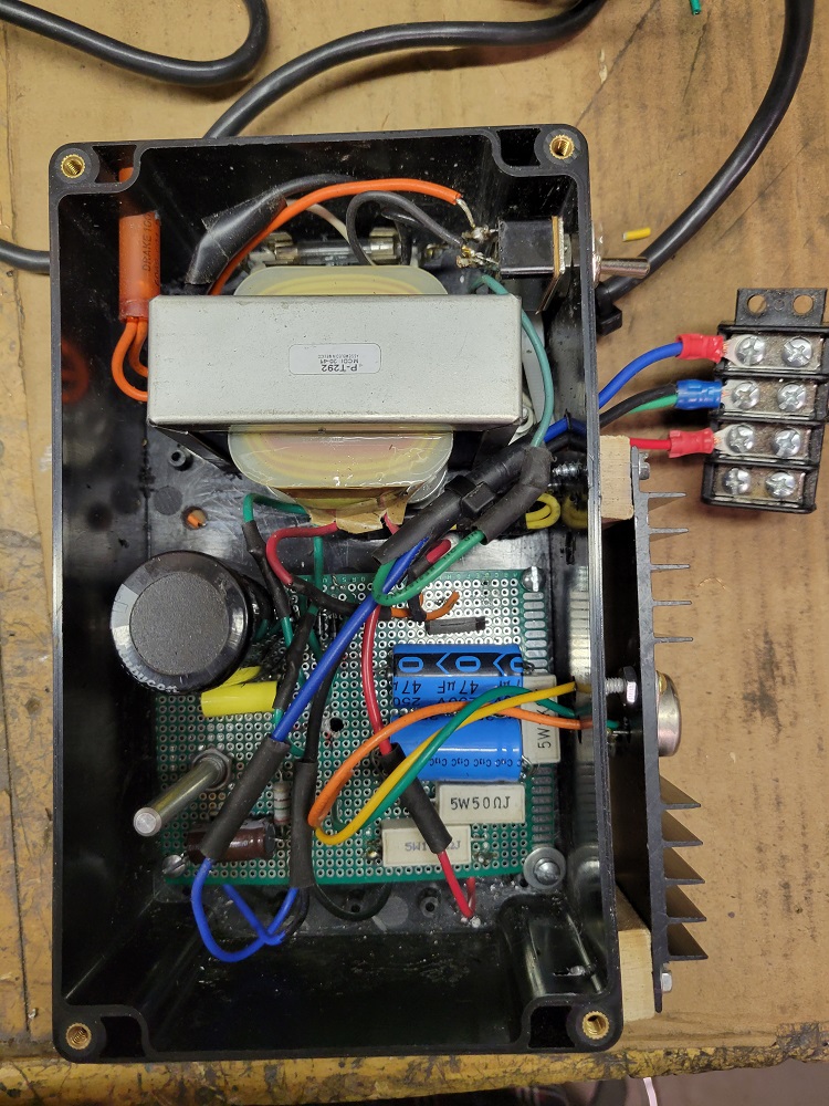
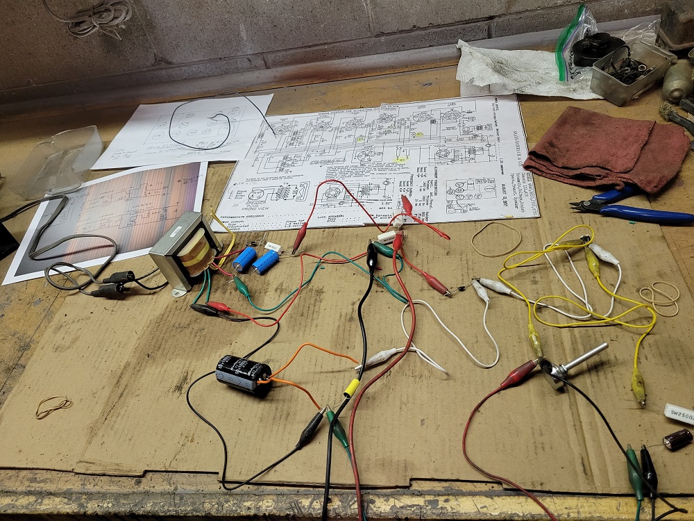
And here are some pics of the radio itself and the power supply mounted inside the cabinet:
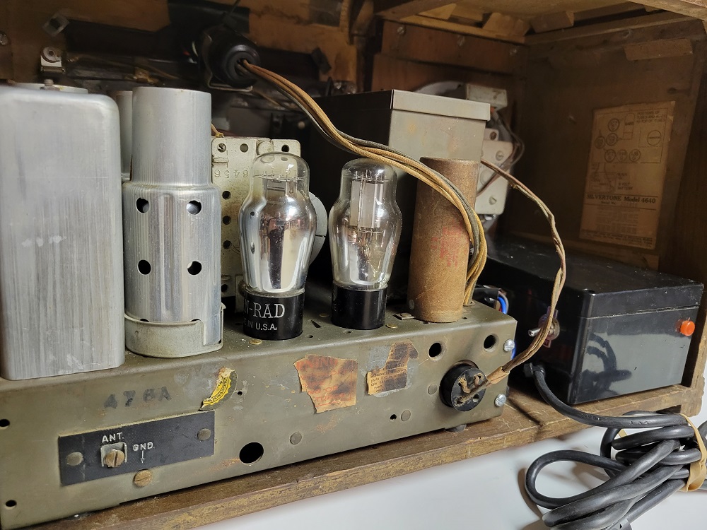
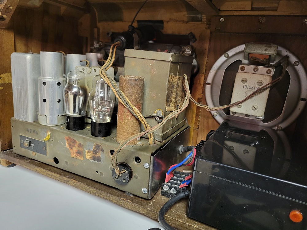
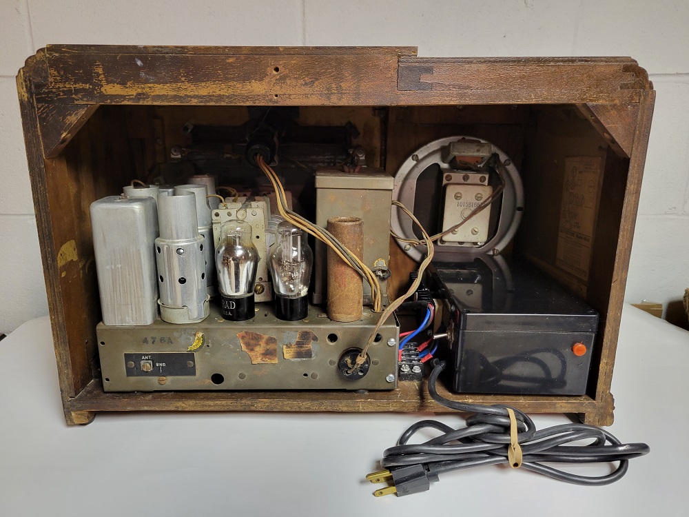
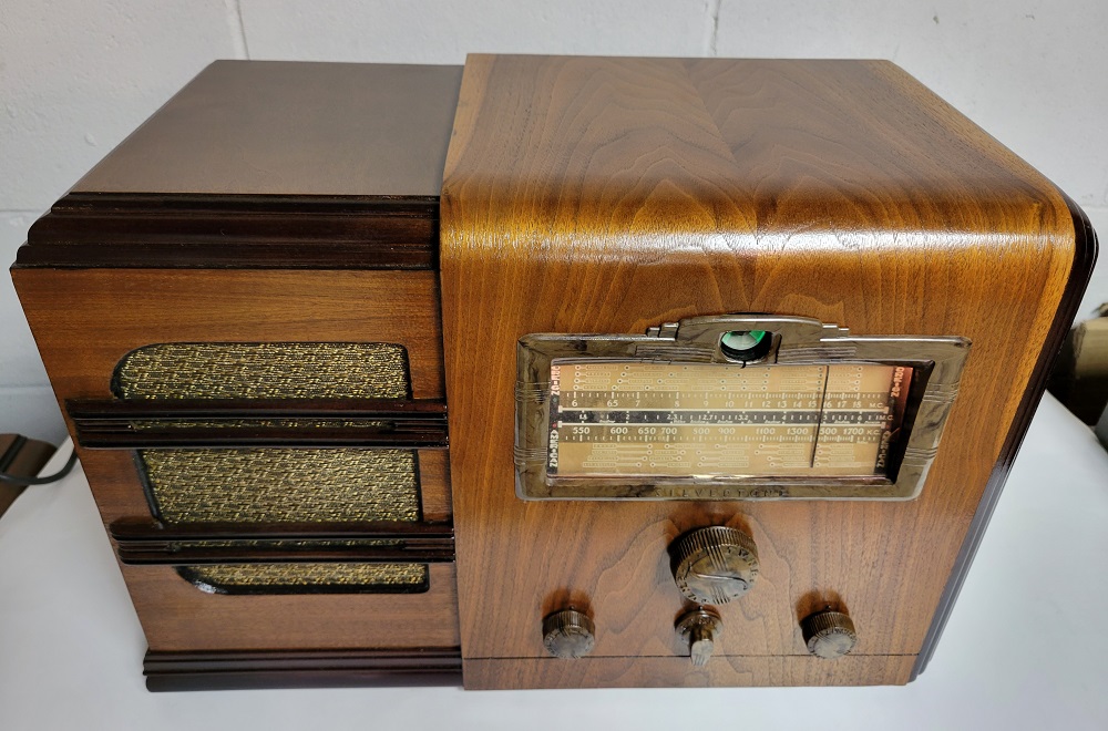
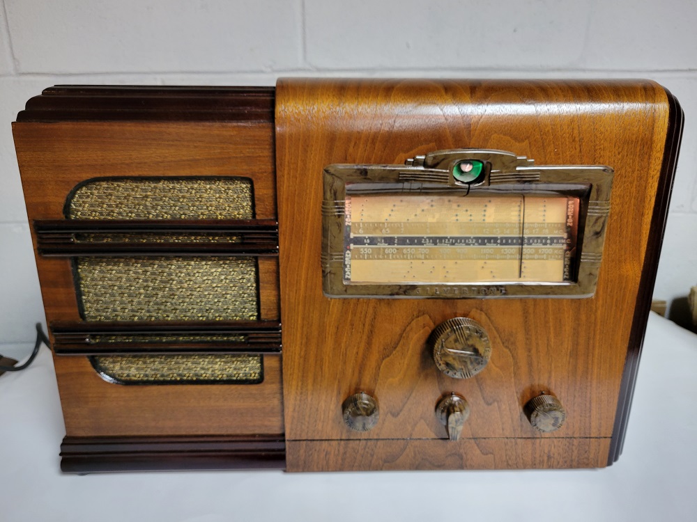
Anyone who has a farm set they'd like to get up and running on AC without batteries, hang on to Terry's design. It's a handy thing, works like a charm, and is a fun little project to build!
For those following along, on his original Power Supply design, the only changes made were:
The IN4007 diode was replaced with a Full Wave Bridge Rectifier for the HV
TWO IN4004 diodes for the Filament side were used in parallel to get 3A out of them.
The LM317T Adjustable Voltage Regulator was replaced with a LM317K, along with the heat sink that was designed for it, and heat sink paste to dissipate the heat. VERY important as it gets very hot otherwise. It's rated for 1.5A and the radio itself is 1.35A so it's getting close to it's limit.
I used a 10K mfd @ 50v e-cap instead of the 5K mfd , 20v that Terry specified, as I had one on hand.
For the voltage divider resistors, I used a 50 ohm on top, and a 10K ohm on the bottom, which calculated to 139v output.
It's also VERY important to have a good ground and keep the leads as short as possible. I had a terrible garbled sound problem that was all related to my having everything just "gator" wired together prior to mounting it in the enclosure. Once everything was properly soldered, it plays nice and clear.
In an unrelated problem, the bias cell batteries were naturally dead, so I tried dropping them in boiling water to recharge them. It kinda worked, but I was only getting .8 volts out of them. So I made a copper plug for the cups and a surround to isolate the sides of the battery (which are positive) from the sides of the cup and replaced all of them with #13 hearing aid batteries. Those are 1.45 volts, more what the original ones should have been.
So here are some pics of the power supply in process:
And here are some pics of the radio itself and the power supply mounted inside the cabinet:
Anyone who has a farm set they'd like to get up and running on AC without batteries, hang on to Terry's design. It's a handy thing, works like a charm, and is a fun little project to build!
Greg V.
West Bend, WI
Member WARCI.org


![[-] [-]](https://philcoradio.com/phorum/images/bootbb/collapse.png)


