Restoring Philco 38-12 in a wood cabinet
Posts: 16,533
Threads: 573
Joined: Oct 2011
City: Jackson
State, Province, Country: NJ
I am eventually back in my workshop, after 10 months of suffering through the repair and the consequences of it.
This radio was acquired by me for a very reasonable price of upward of $40 a year ago, during the Kutztown show of 9/2023.
I am trying to assemble a collection of 38-12, towards which I already have a brown backelite one.
I could also count the 38-15 in a wood cabinet I have towards it, as these two radios are exactly the same, with a SW antenna coil and the switch for it added.
So I bought this wood cabinet one, and a wood white-painted (the factory painted) one.
I would love to have the Plaskon one too, but they are exceedingly rare. Ron bought one and it came broken, so he had to glue the case together and then refinish it.
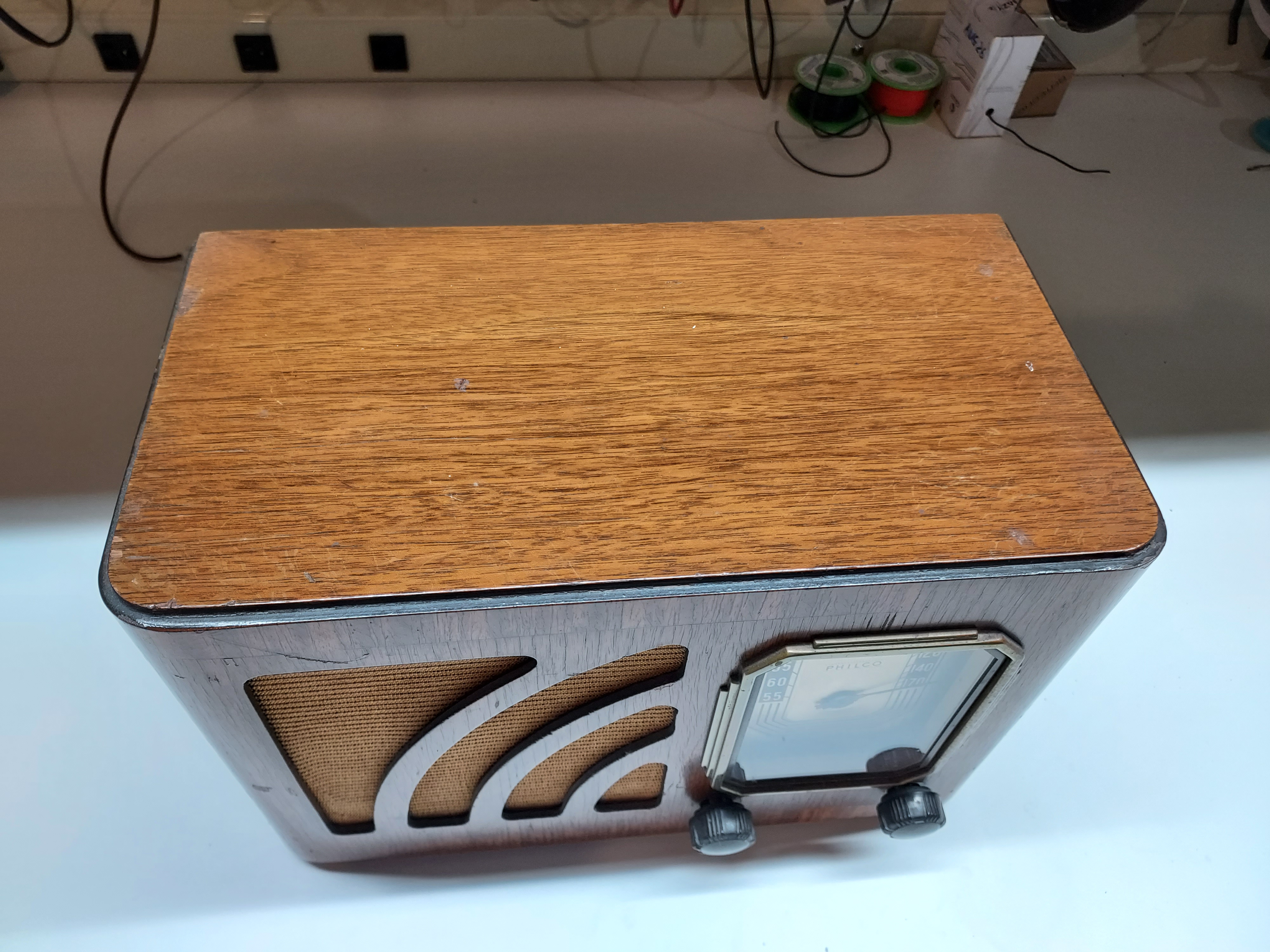
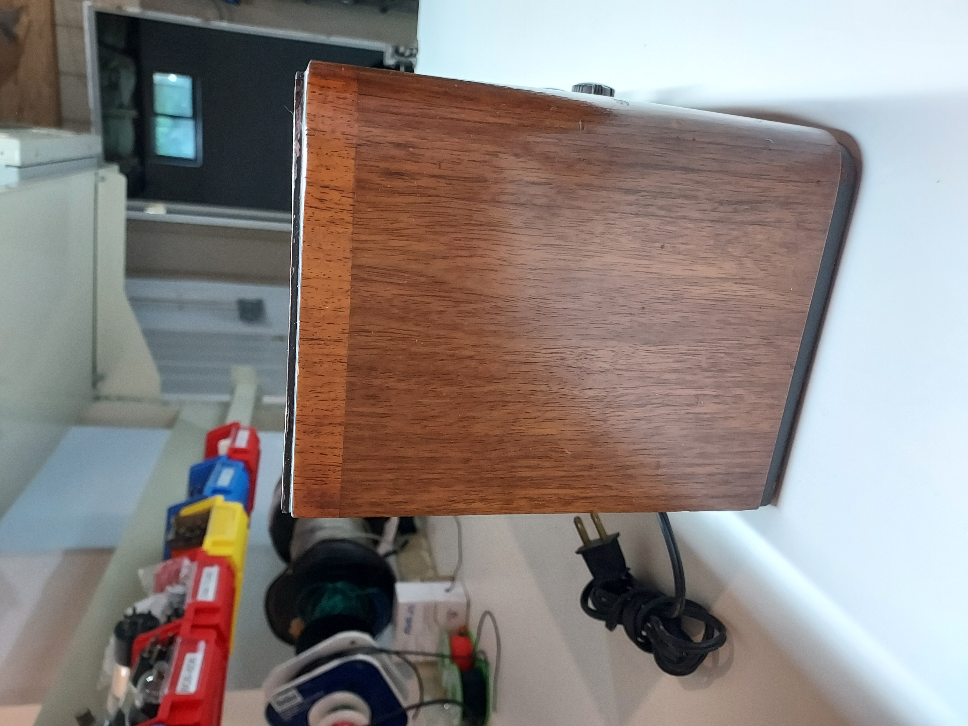
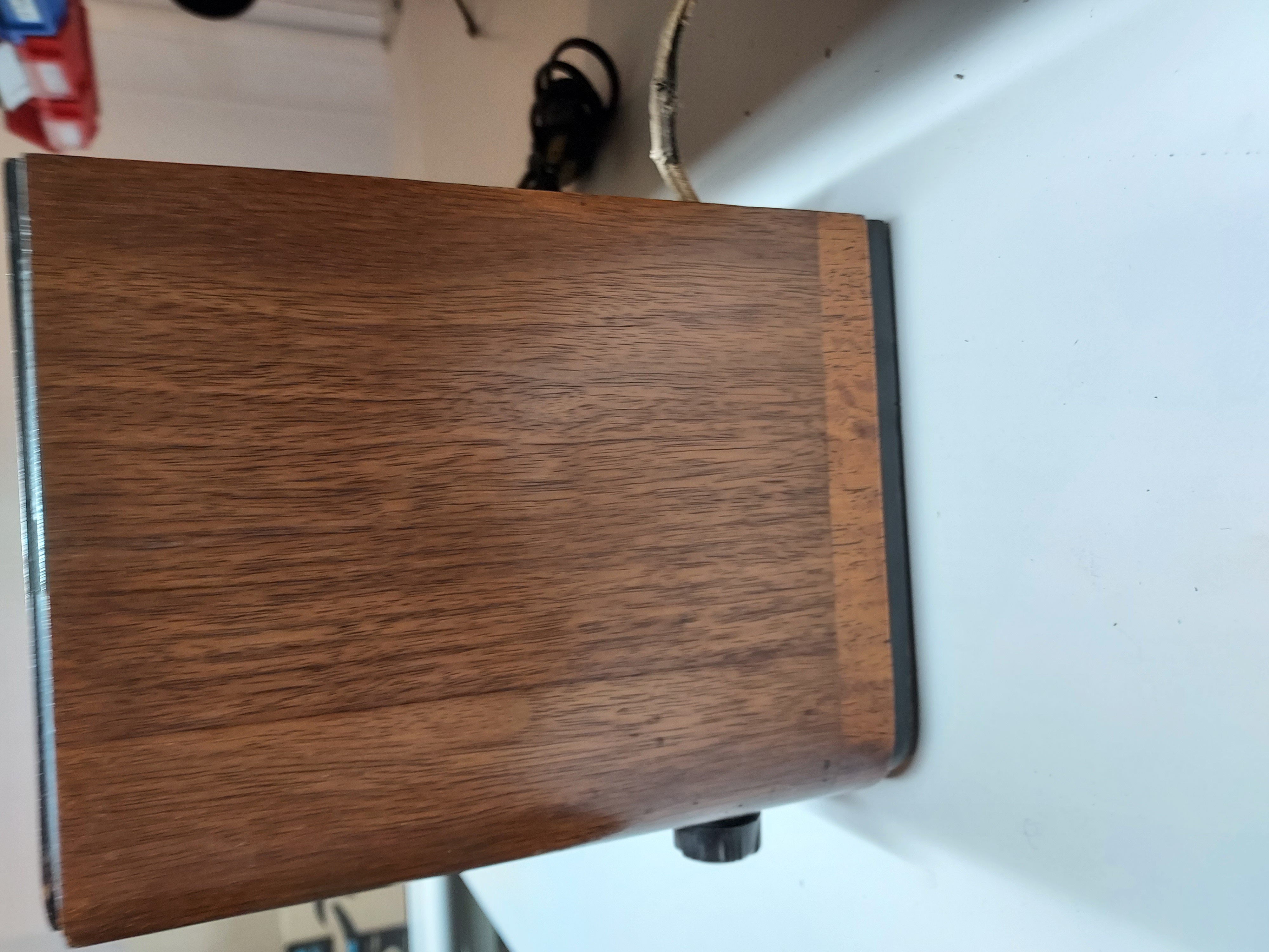
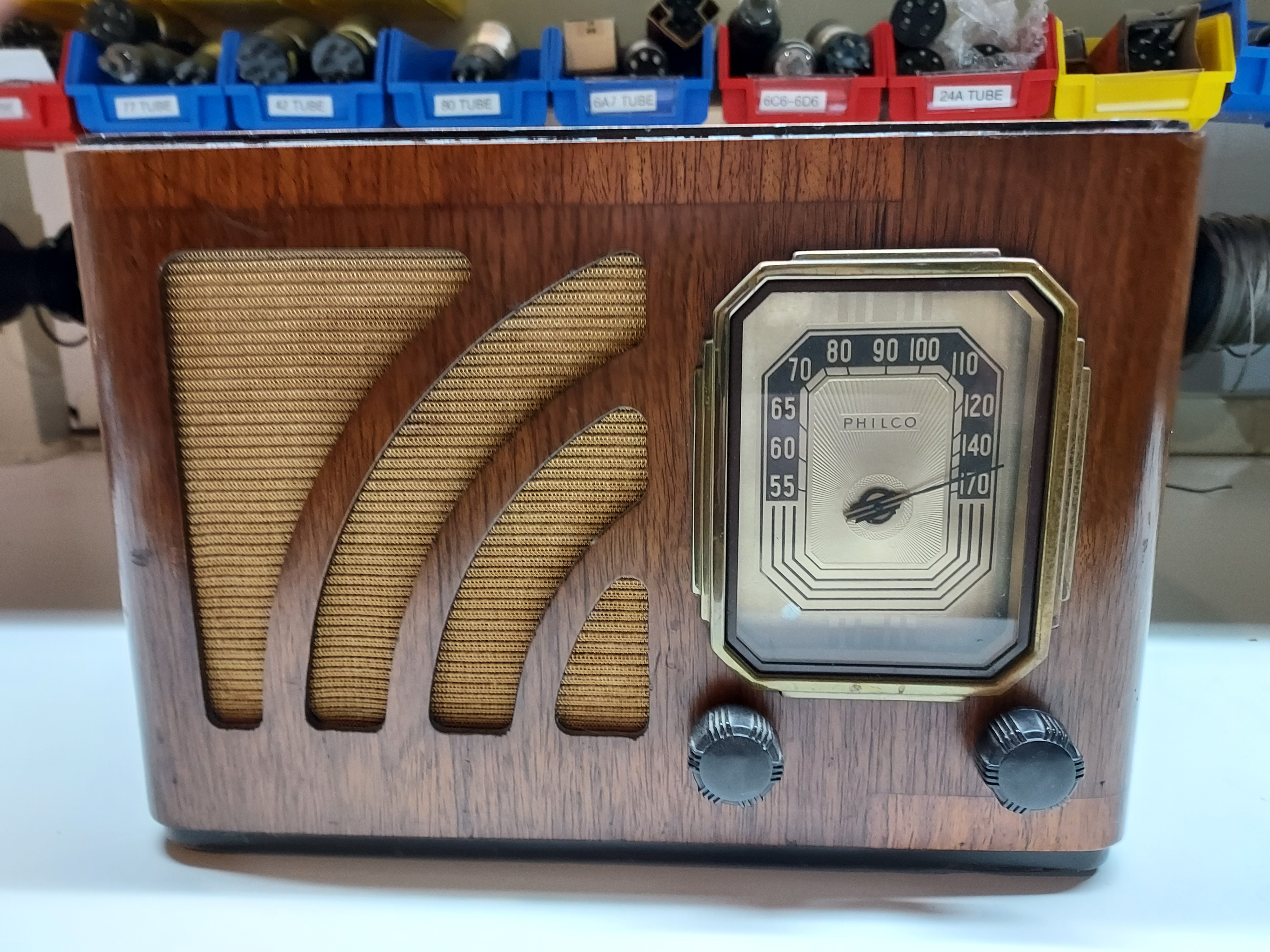
Anywho, the shape of both the case and the chassis of this one are excellent, and I don't think I will be doing anything to the cabinet.
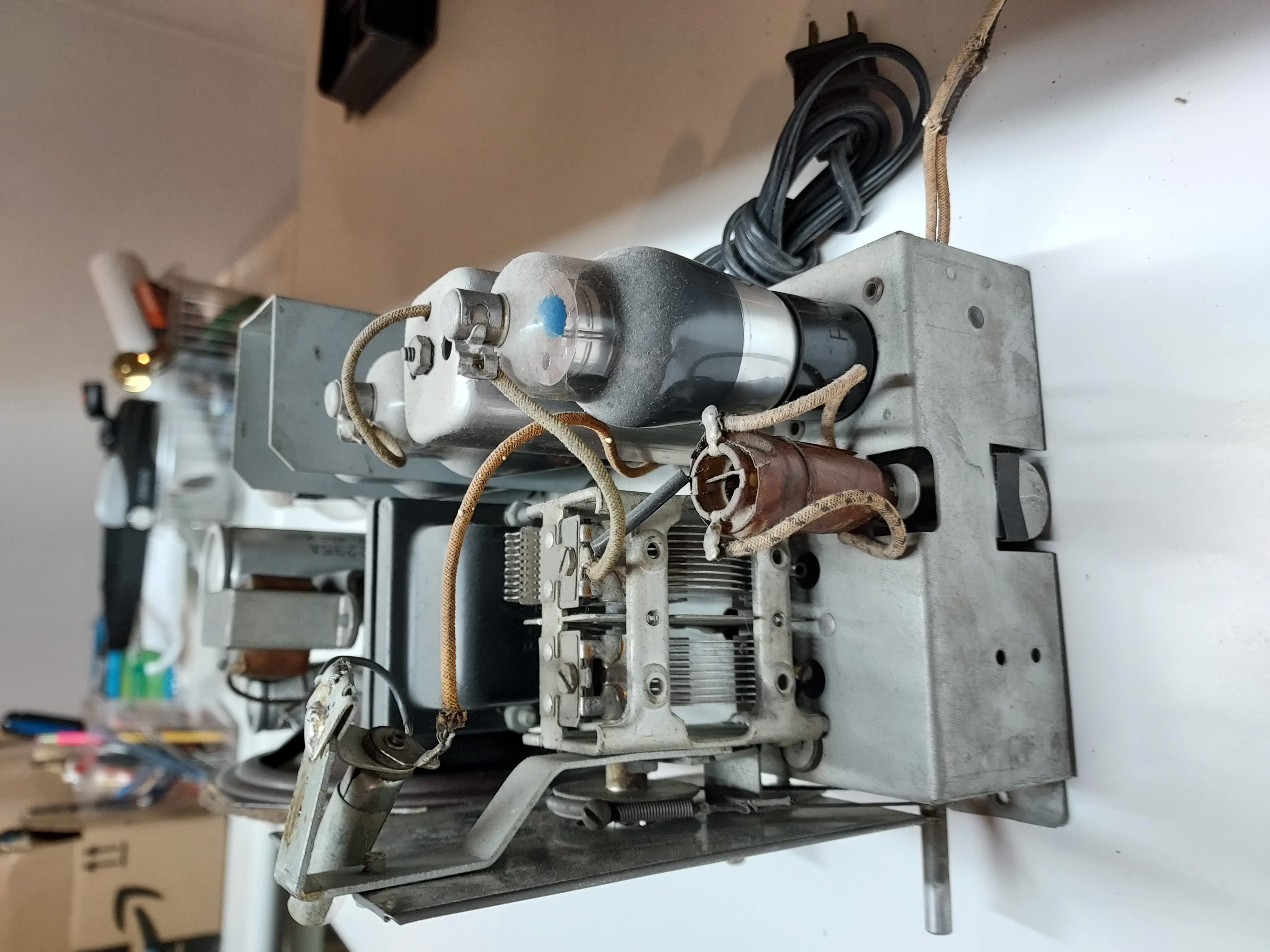
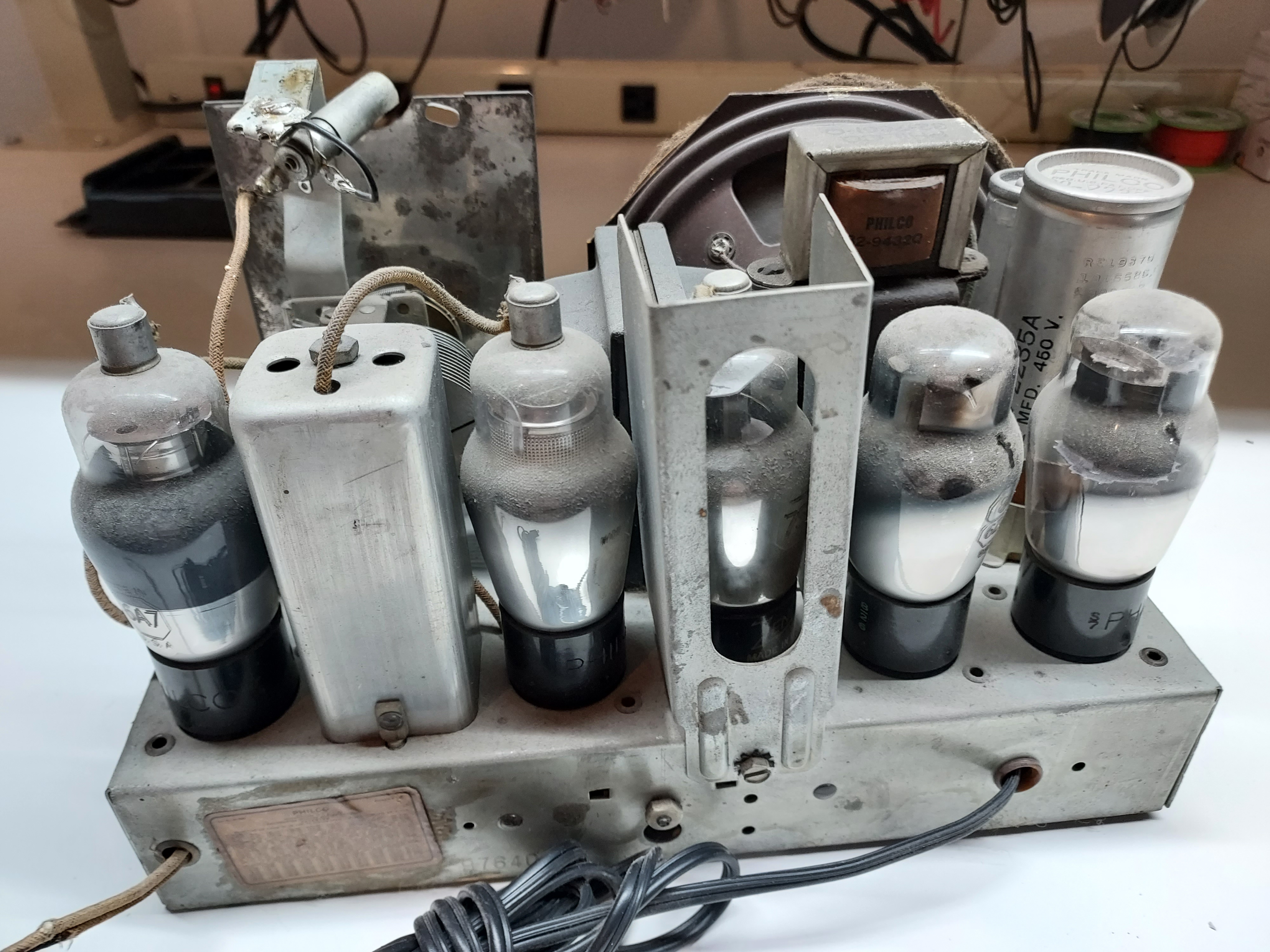
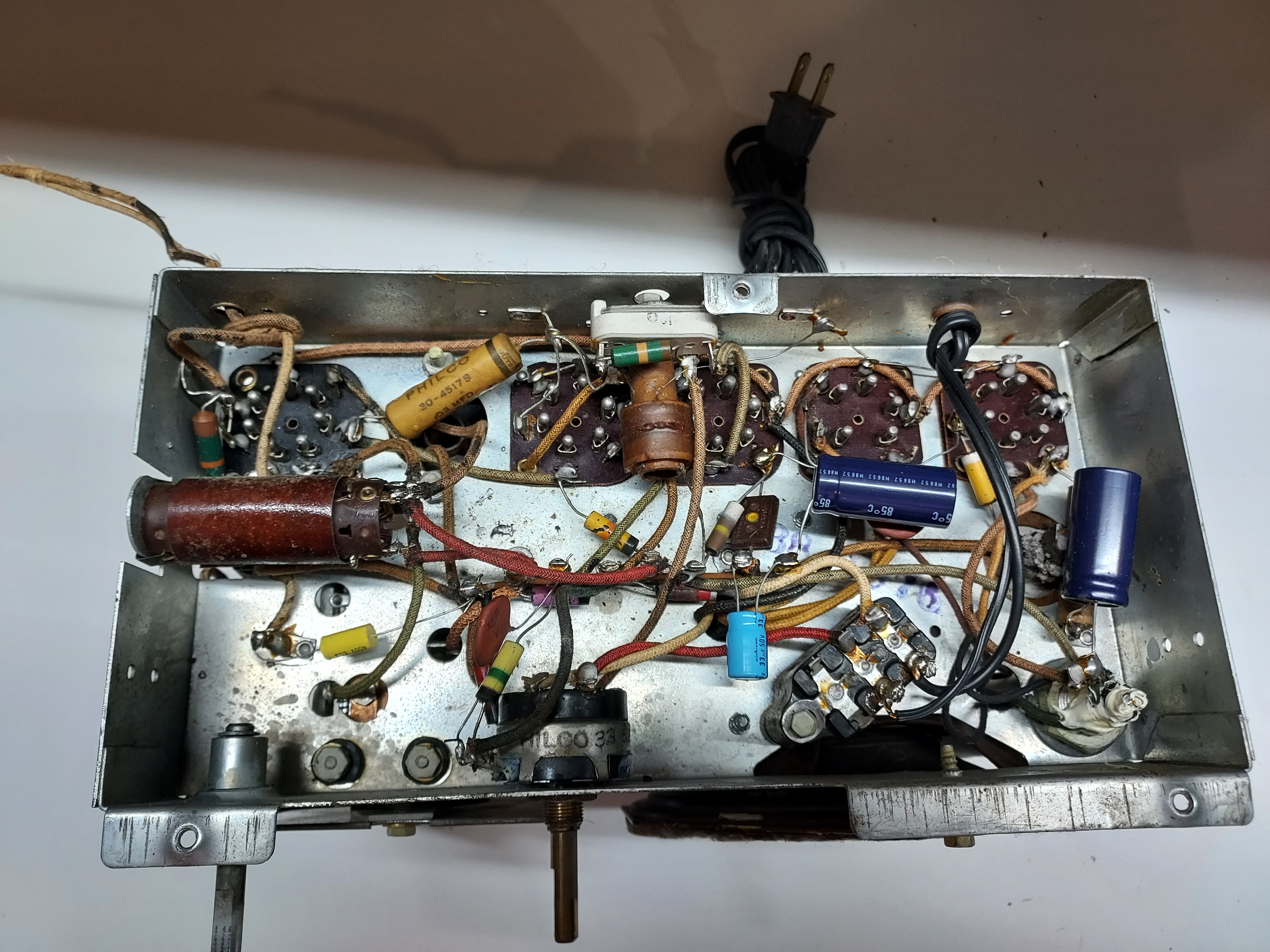
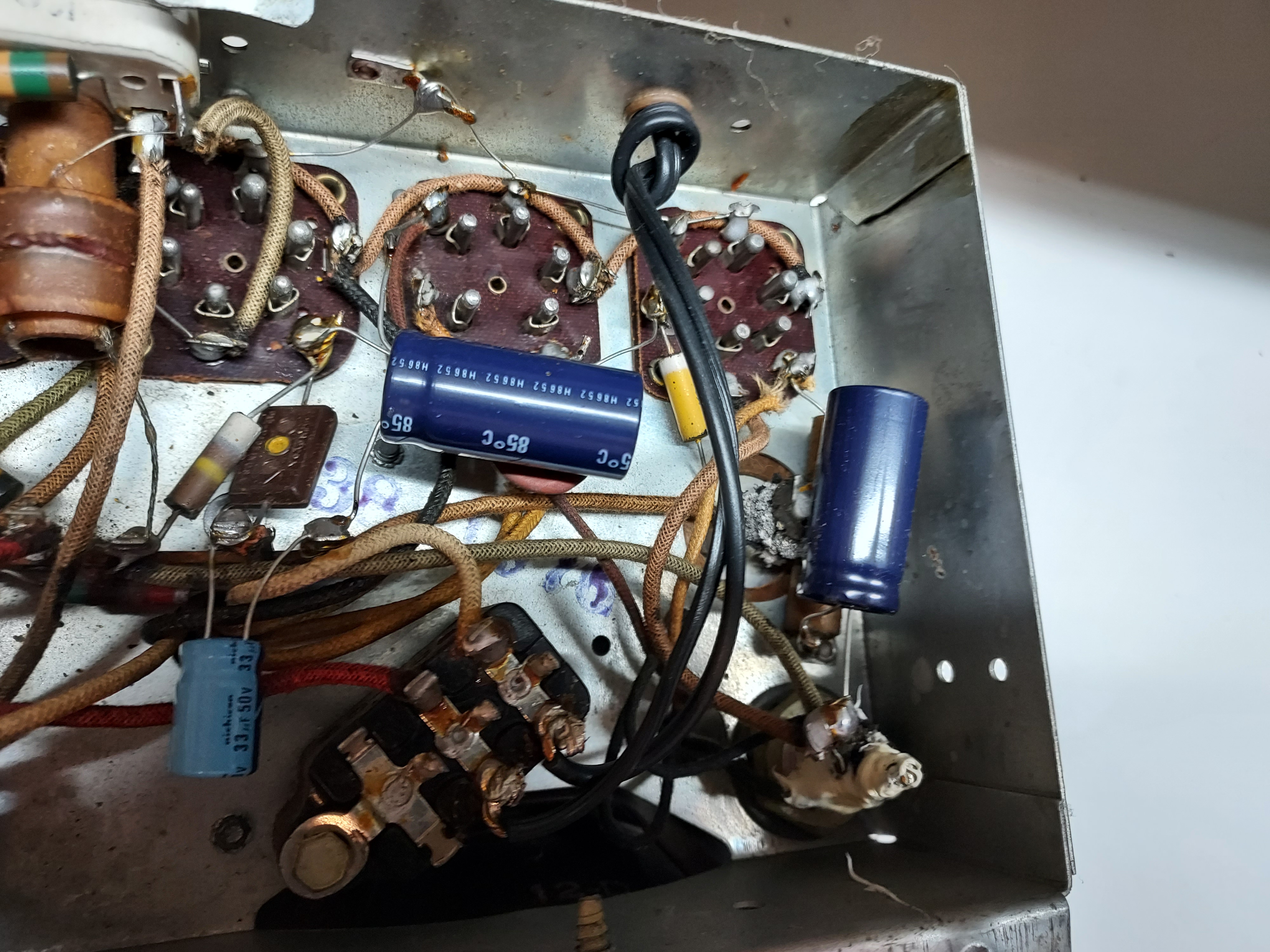
The chassis is very clean, and, though I do not like it, it was restored at some point. Not to my standards, but it is, all in all, a good restoration. It's just I am not a fan of hanging caps and electrolytics over the existing old parts. Even if it is properly done (they are).
After having realized the radio has been restored, I simply plugged it in, and it worked OK. It pulled in our local station, fairly clear. It has some "motorboat-like" hum, which only exists when the station is not on. It is not motorboating, per se.
Then I tested the tubes. All, except the rectifier (84) are in good to excellent shape. The rectifier was not just weak. It was VERY-VERY weak. And it still worked. Luckily, I bought a few junkers a couple of years ago, one of which was 38-12, and the tube in it was super-good, tested like new. This said, it made very little difference in reception.
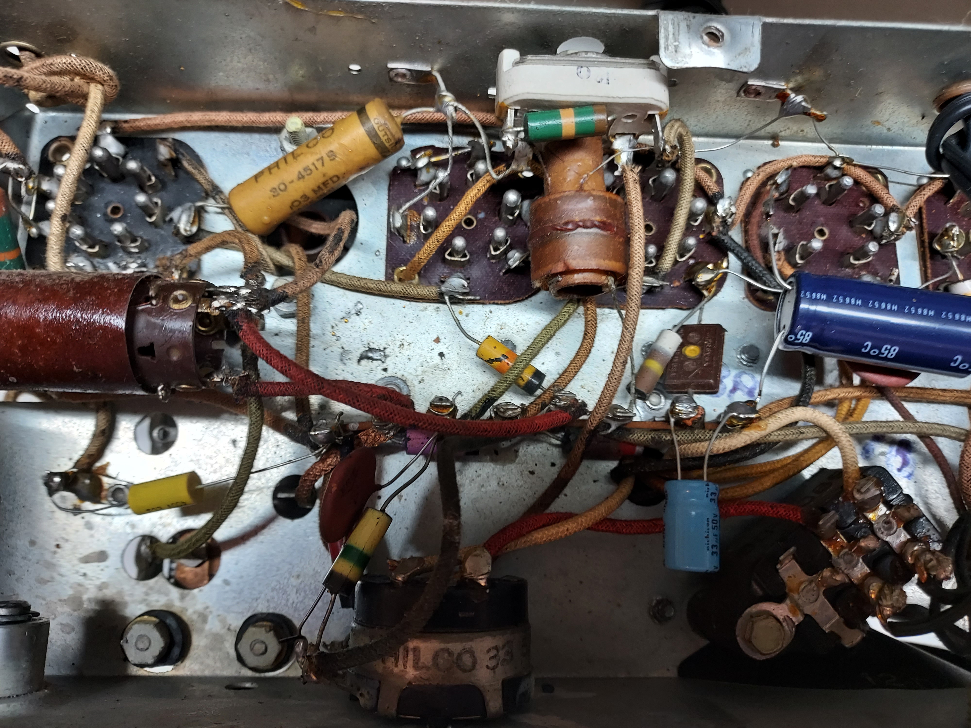
As seen from the photos, not all caps have been replaced. I intend first to replace all of the original caps, then tackle the electrolytics and those that are outside of the backelite etc.
This is the first photos, the case and the chassis.
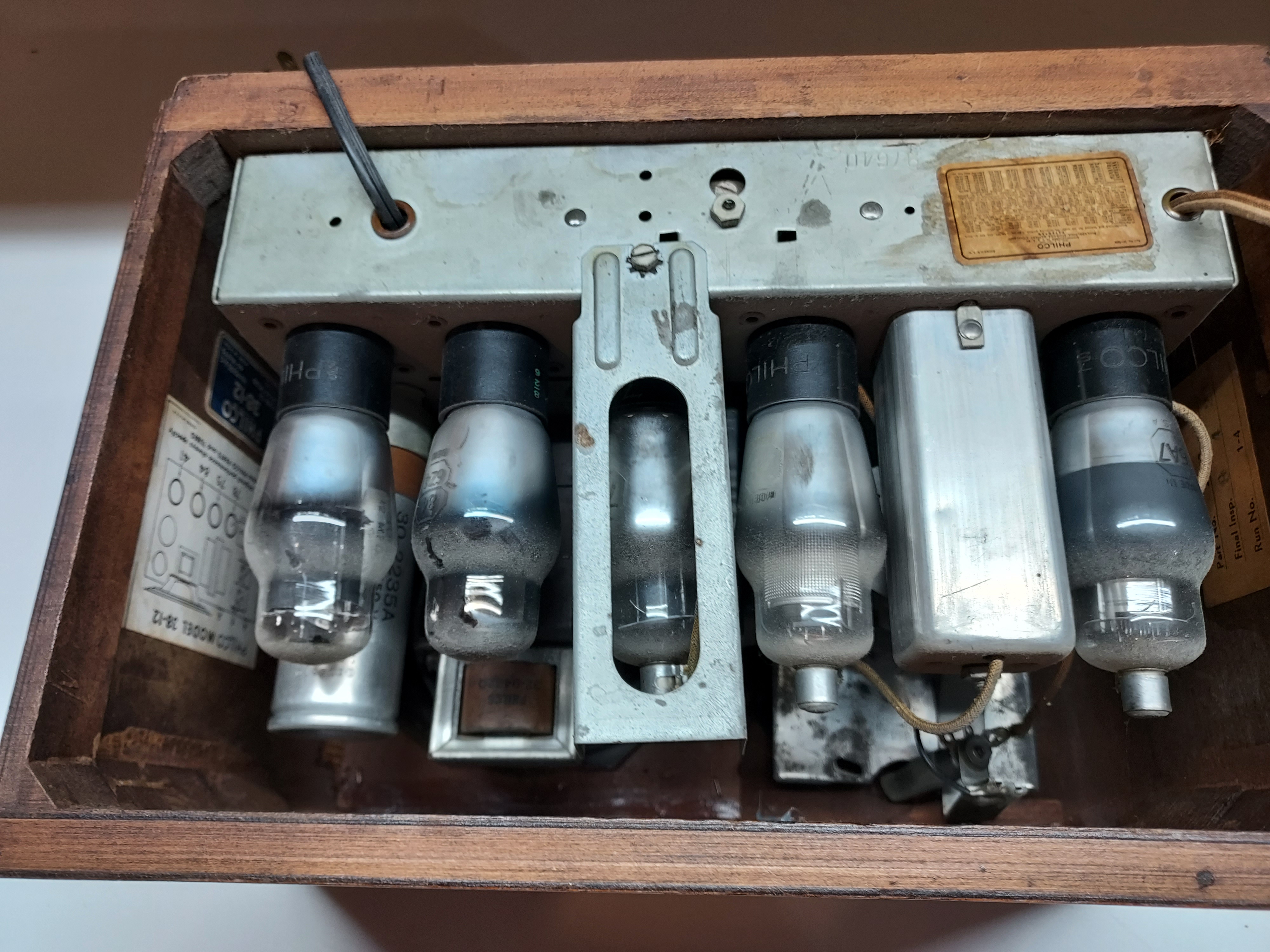
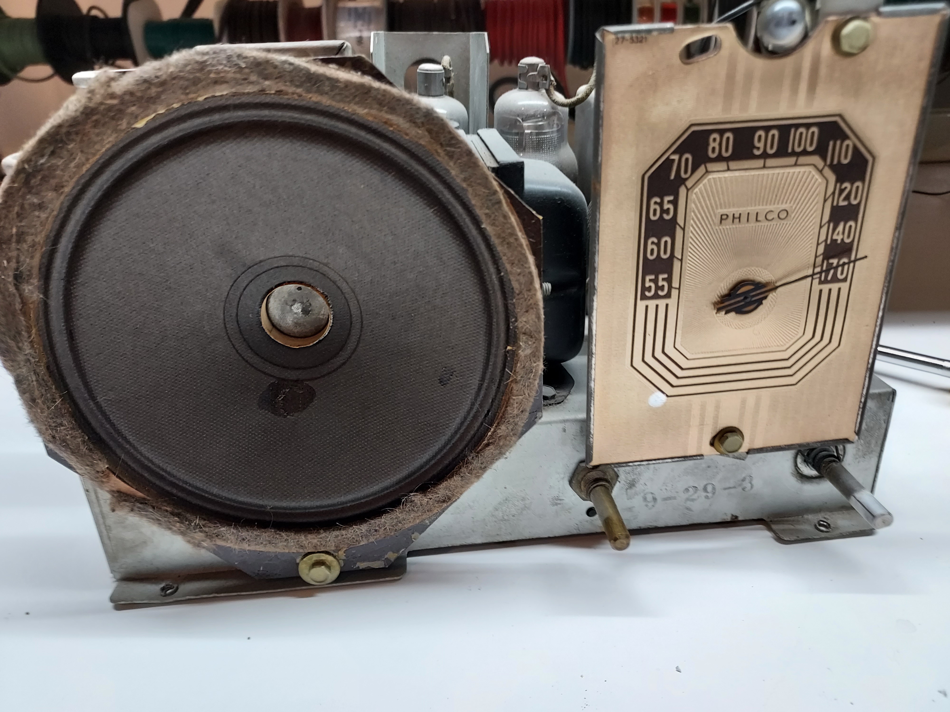
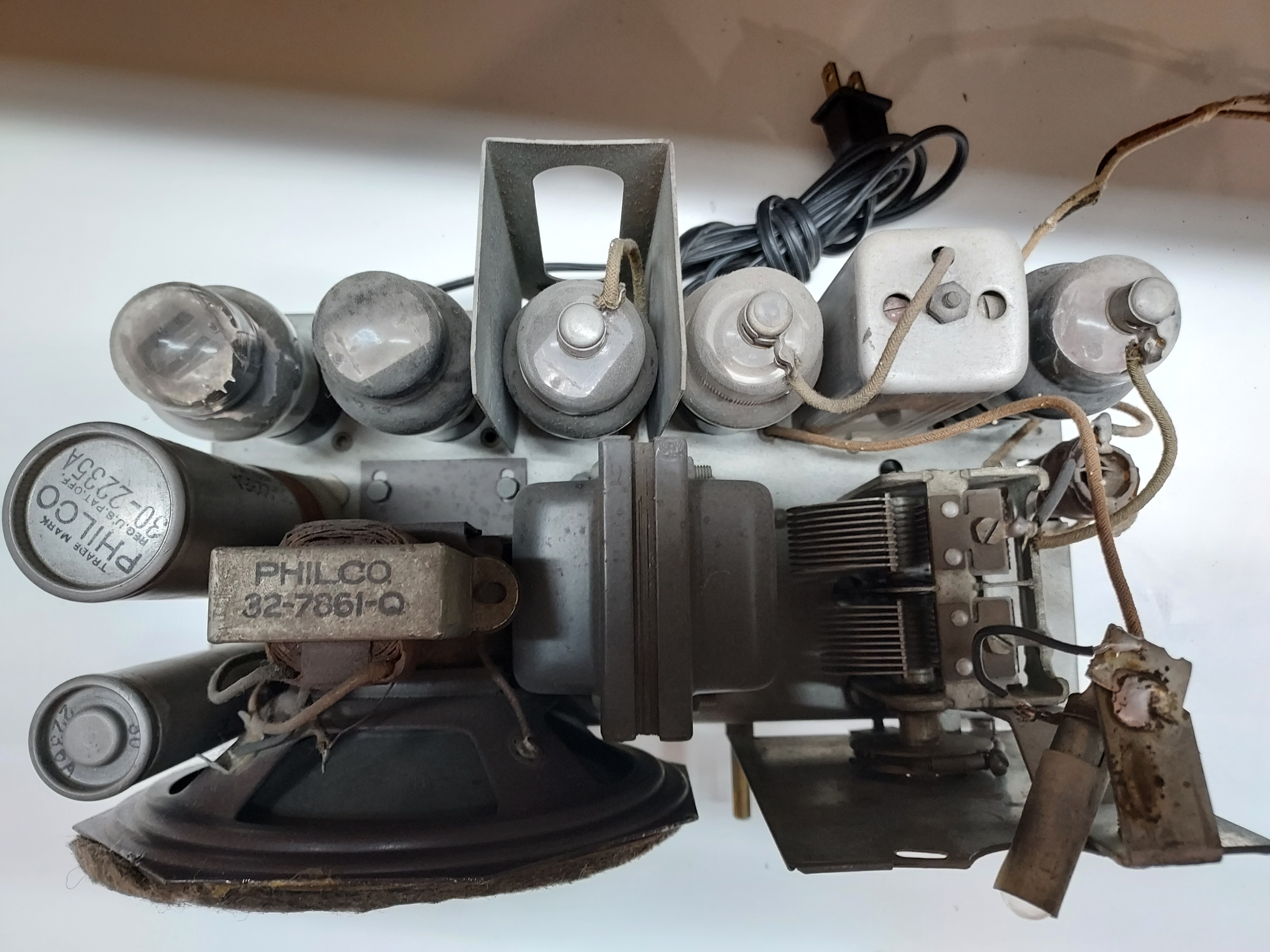
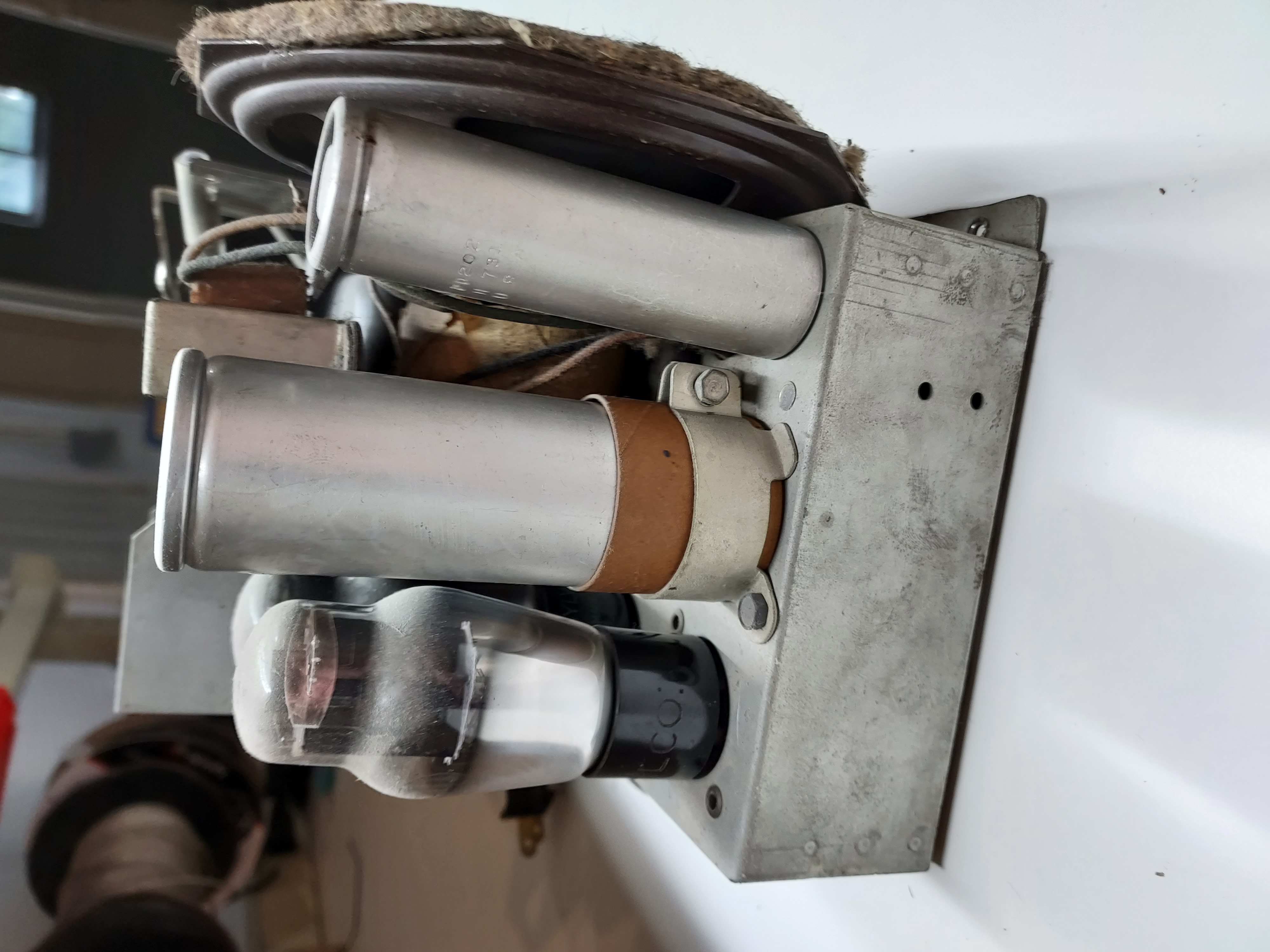
People who do not drink, do not smoke, do not eat red meat will one day feel really stupid lying there and dying from nothing.
Posts: 16,533
Threads: 573
Joined: Oct 2011
City: Jackson
State, Province, Country: NJ
Today I :
- stuffed the old tubular caps
- stuffed the backelite block (two Y-caps), and
- replaced the disk ceramic caps and the sole axial film one with the old caps' shells with axial caps inside.
- Plus Iremoved the 30uF 50V cap that was there between the GND and the Negative. It is not in the schematic, so even if it is good, I do not want it. Plus it seems it did not affect anything in a negative way.
The radio works a bit better. I also realized the strong noise (which I never heard before) is coming from my workbench's light fixture, which has a switcher inside.
I also need to restuff electrolitic caps plus fix the values (the 1st cap is 20uF instead of 12uF).
People who do not drink, do not smoke, do not eat red meat will one day feel really stupid lying there and dying from nothing.
Posts: 16,533
Threads: 573
Joined: Oct 2011
City: Jackson
State, Province, Country: NJ
Today I replaced or parallelled (if the deviation was not too large) the resistors.
One particular resistor puzzled me for a while.
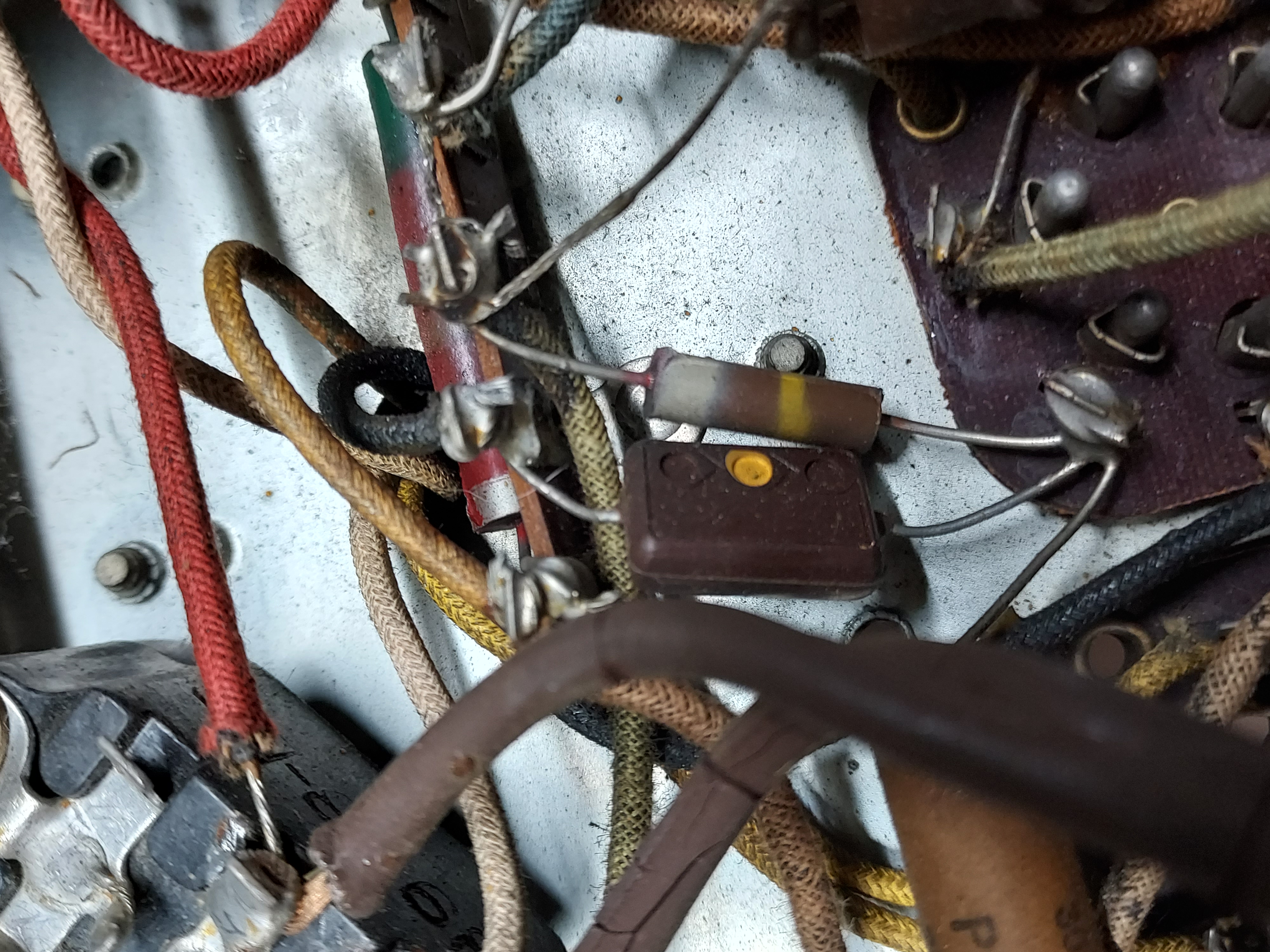
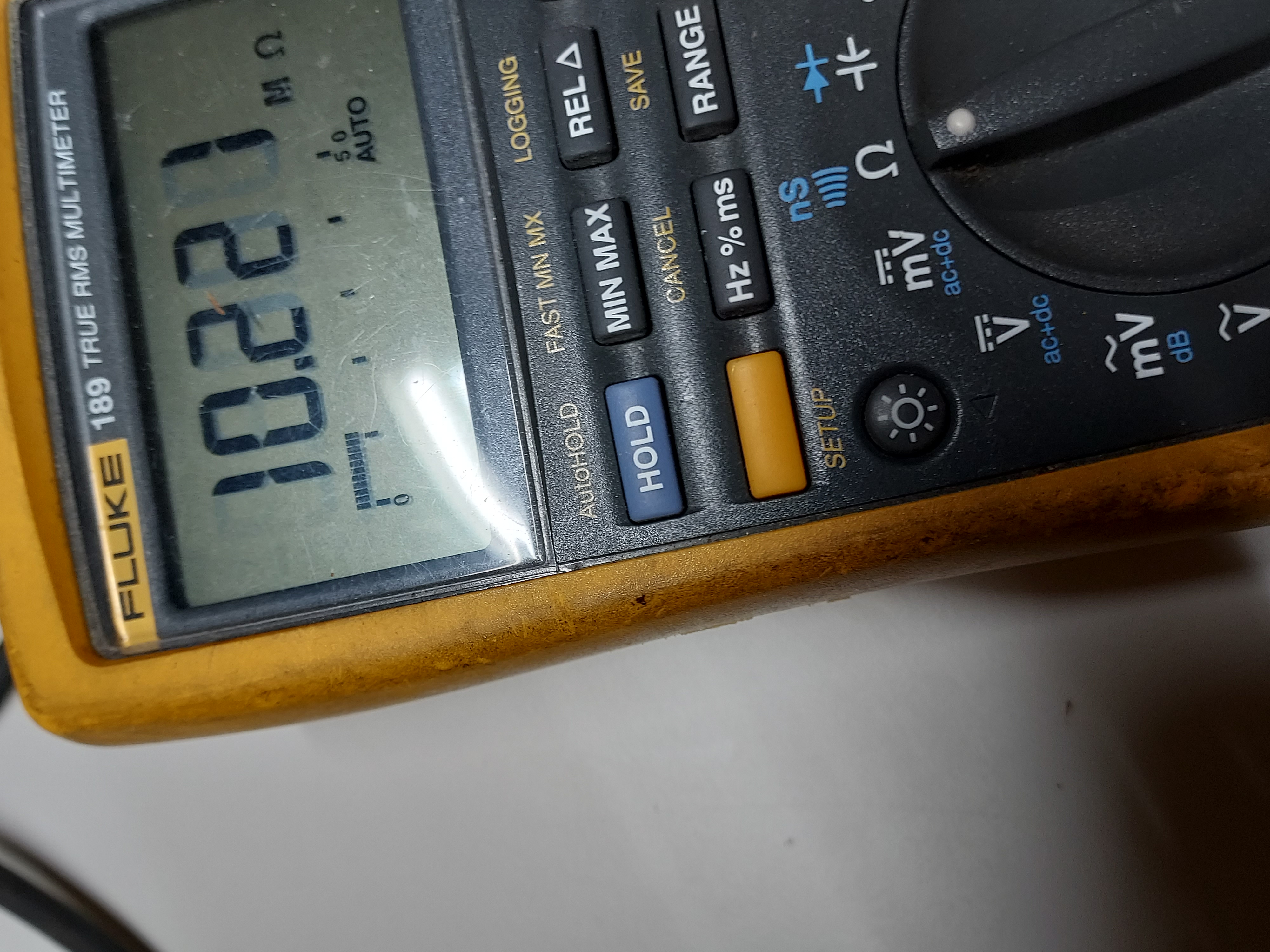
It showed 7.3M and it should've been 190K. I 've seen my share of open resistors...but the radio worked fine.
I have another chassis I keep on the bench for reference; it was acquired independently about 2 years ago for $5. In good shape.
So, I looked at the same resistor there, and it showed....10M. I started doubting myself. I even thought it was some variation. I tried to look for 190K resistor but to no avail. Then I measured the voltage on the plate of the IF, where that resistor was the load, and saw 20V instead of 90V.
So I replaced it, and the voltage came back normal. The radio worked the same way as before.
I never saw two resistors in two chassis failed the same way. Bad batch?
Spare chassis' resistor
Its resistance
My chassis' resistor
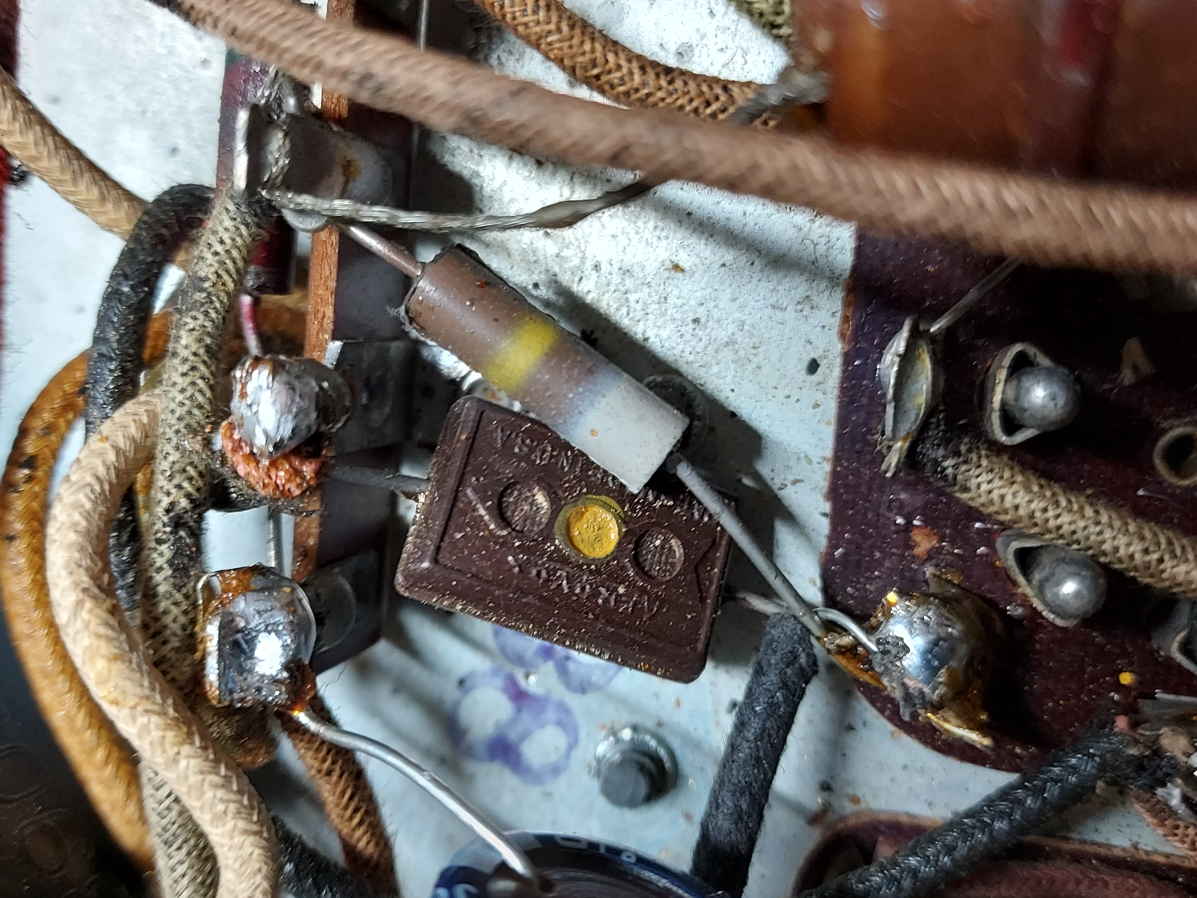
Its resistance
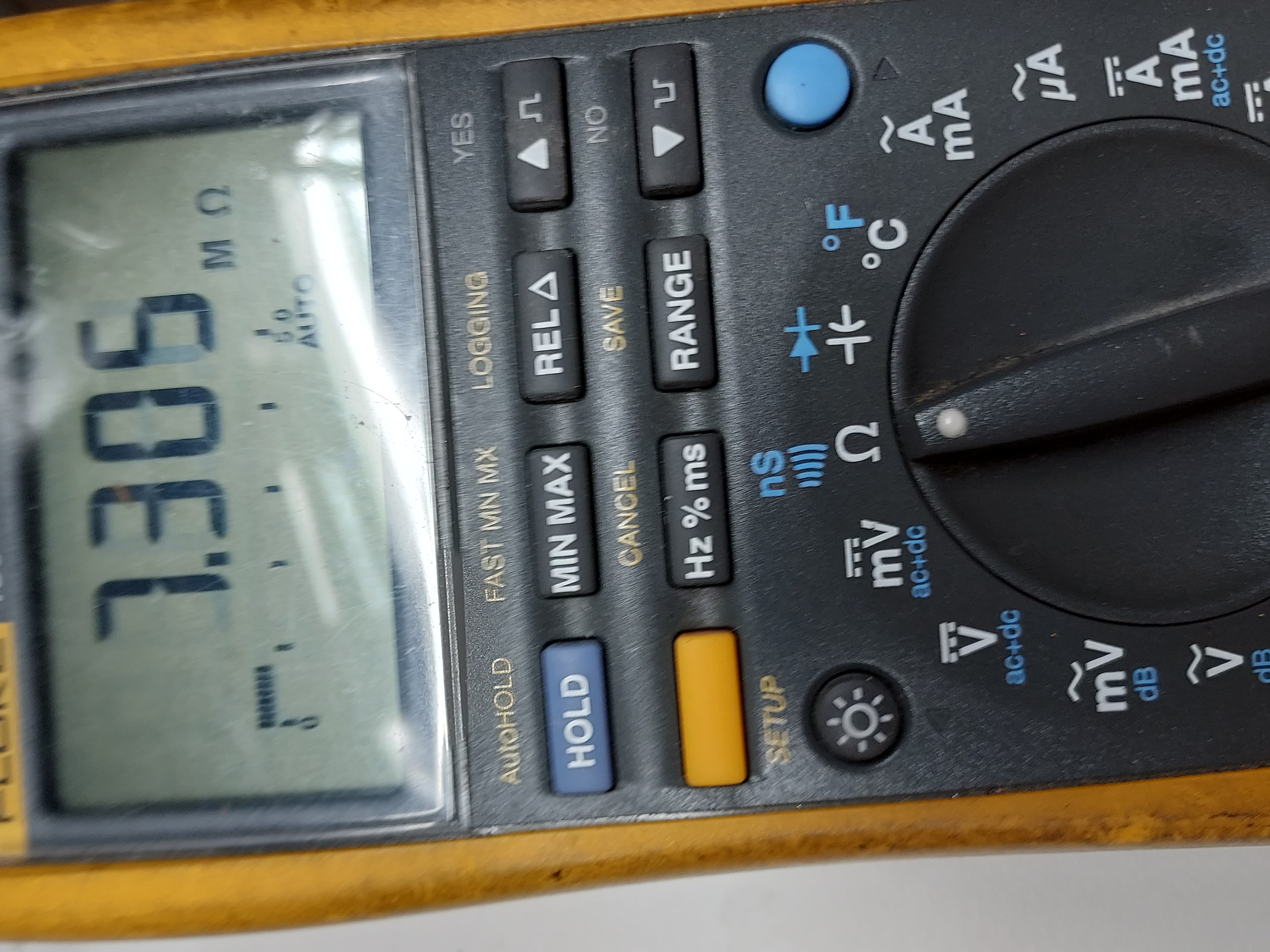
Now just replace the electrolytic caps.
People who do not drink, do not smoke, do not eat red meat will one day feel really stupid lying there and dying from nothing.
Posts: 16,533
Threads: 573
Joined: Oct 2011
City: Jackson
State, Province, Country: NJ
Attempted to extract the electrolytic caps; the corner one would not come out. The previous guy put some hermetic over, and none of my pliers or adjustable wrenches fit.
I ordered some deep sockets I do not have: 7/8/ 13/16 and 1" - good reason to order, and I am sure, one of them will do the job. They promise Thursday delivery. I will proceed then.
People who do not drink, do not smoke, do not eat red meat will one day feel really stupid lying there and dying from nothing.
Posts: 16,533
Threads: 573
Joined: Oct 2011
City: Jackson
State, Province, Country: NJ
7/8" socket came yesterday, and then it was a walk in the park to extract that 4uF cap.
Both caps exhibit 70% rise in value, and when shaken, a liquid splashing is heard inside. I take it, they are beyond the repair (reforming) and tonight both will be drained and opened in order to be re-stuffed.
People who do not drink, do not smoke, do not eat red meat will one day feel really stupid lying there and dying from nothing.
Posts: 16,533
Threads: 573
Joined: Oct 2011
City: Jackson
State, Province, Country: NJ
Today I have finished recapping.
The last two days' evenings I spent rebuilding the electrolytics.
First I had to drain them. I drilled two small holes diametrically across the bottom of both caps, one to drain the liquid and the other to let the air in.
After that I cut them open, gutted and soaked in white vinegar to get rid of some deposits and oxidation.
Then I rinsed and dried them, and after all this I started the "gefilte cap" dish.
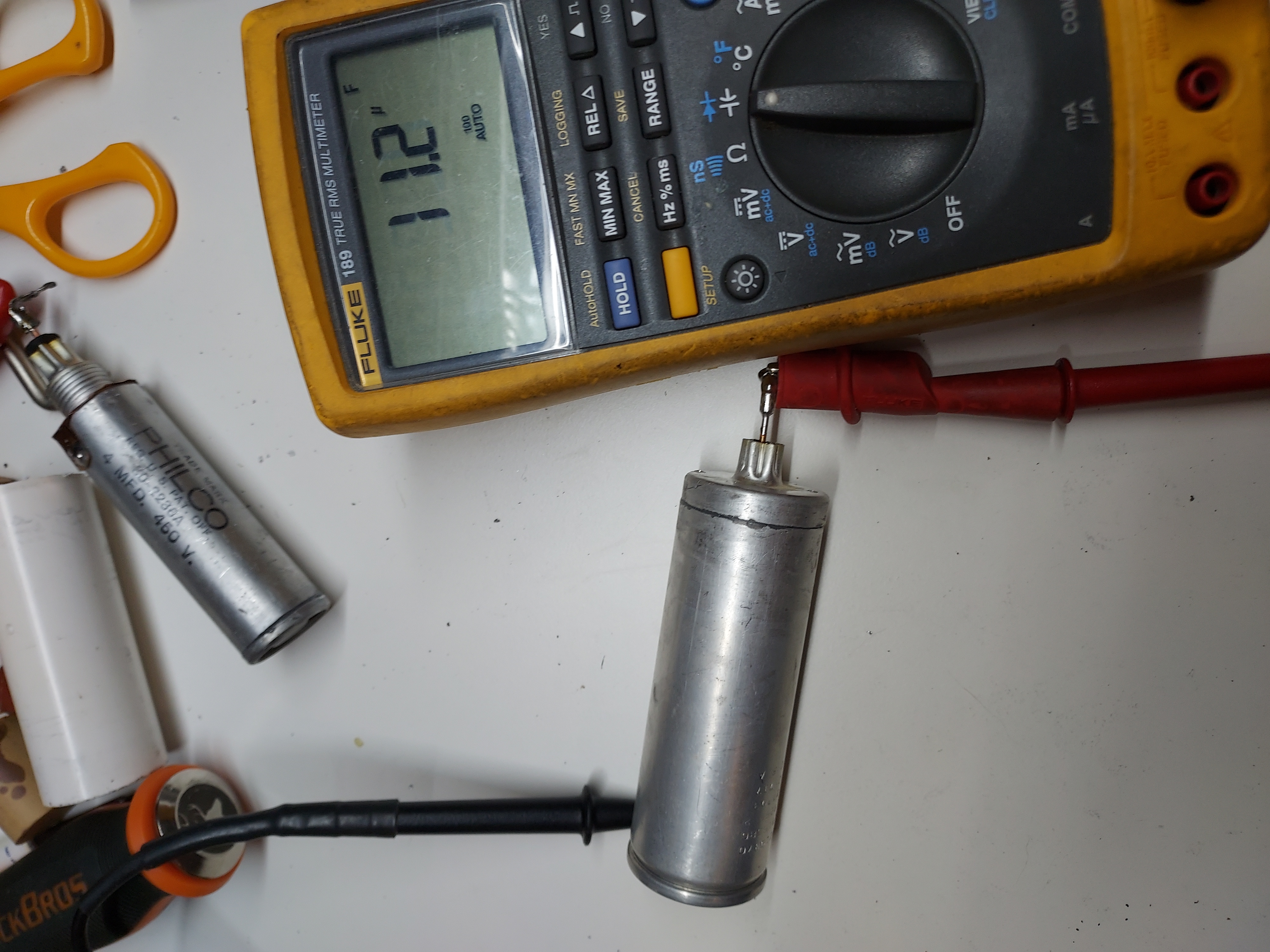
First prep the 12uF cap: serialized two 22uF high-ripple Panasonic capacitors (22uF 450V, 560mA ripple at 120Hz).The resulting capacitance is 11uF, close enough.
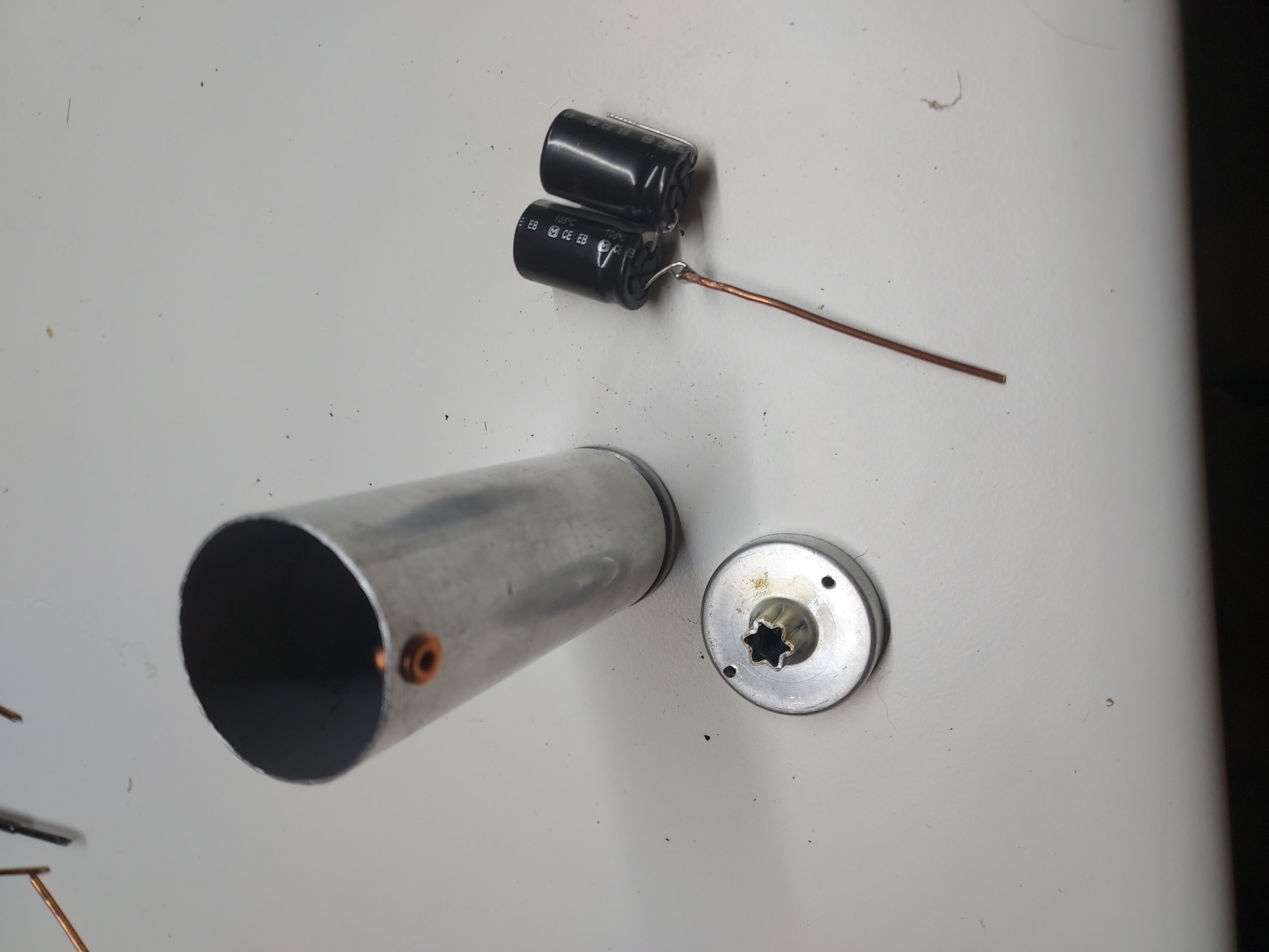
Then wrap it in fish paper (to keep the cases from the shell), push into the shell, and insert two spacers to stabilize it inside the shell (also made from fish paper, a simple roll).
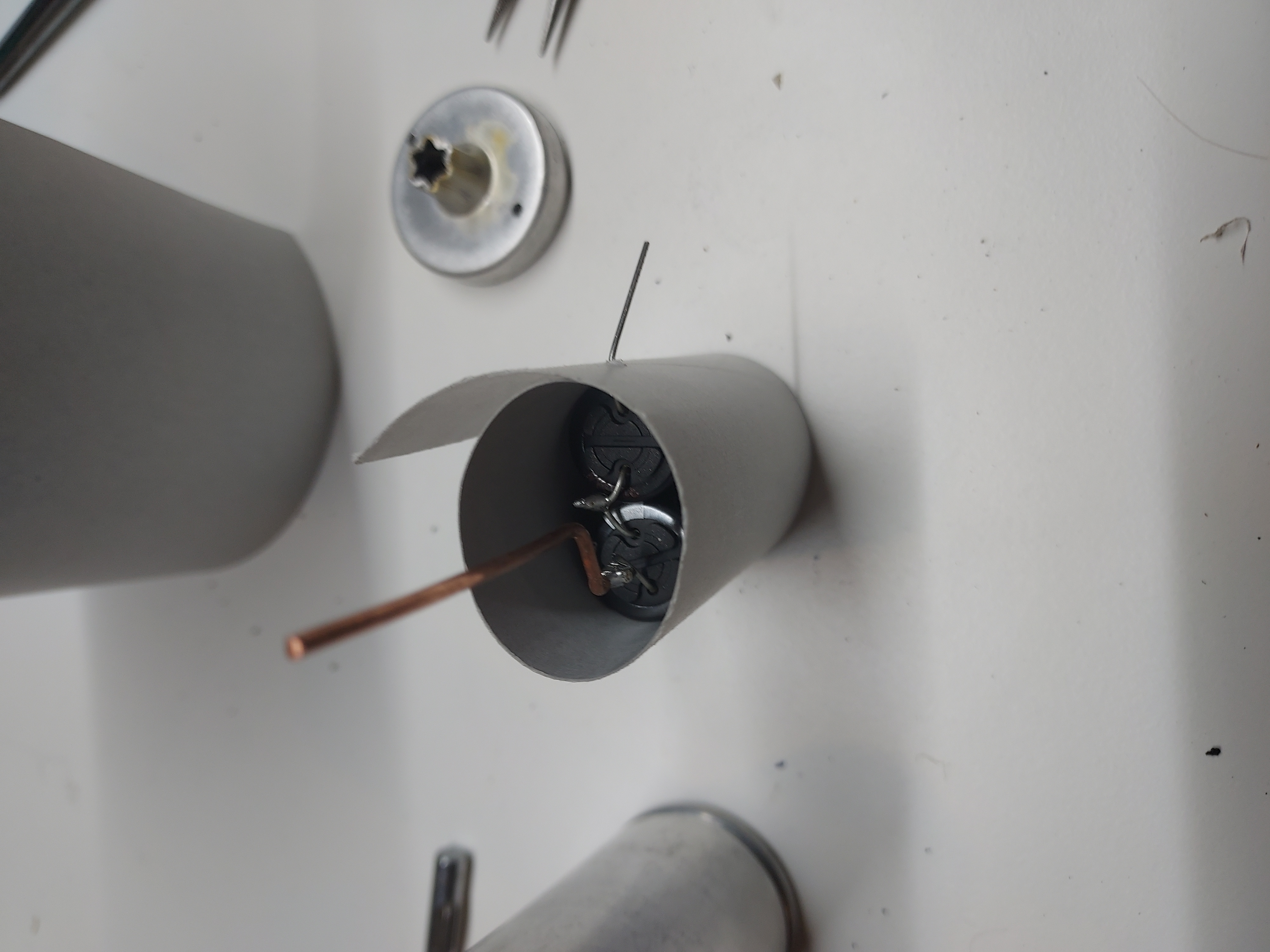
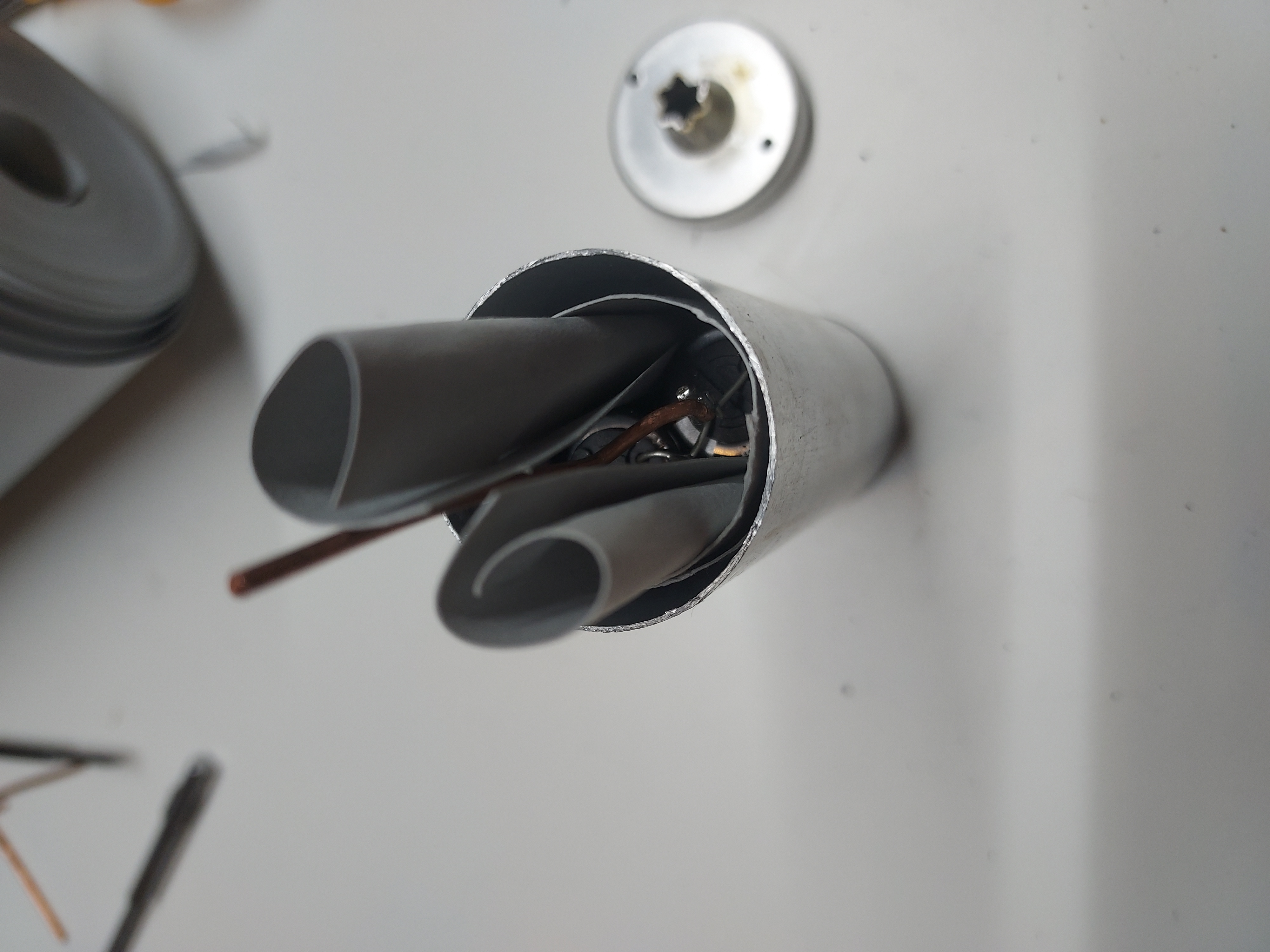
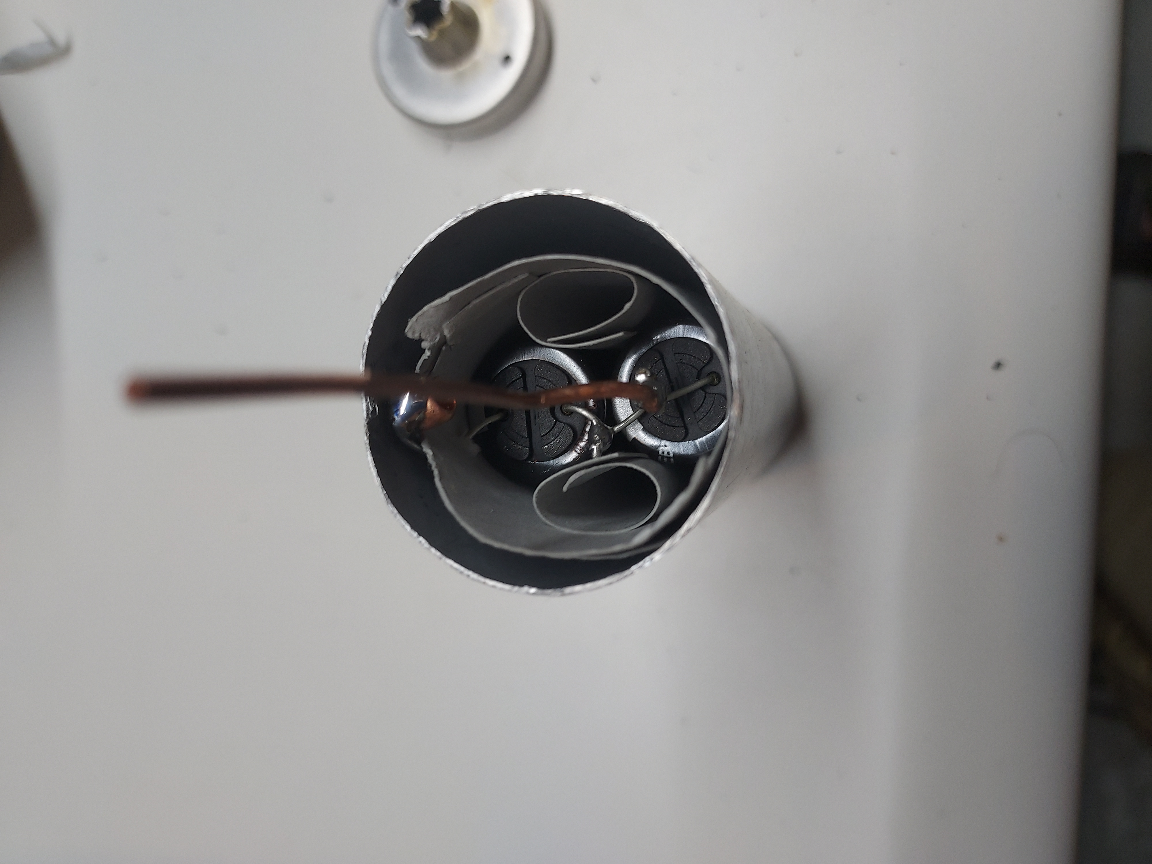
Then I put a copper rivet at the side of the shell, and soldered the negative lead to it.
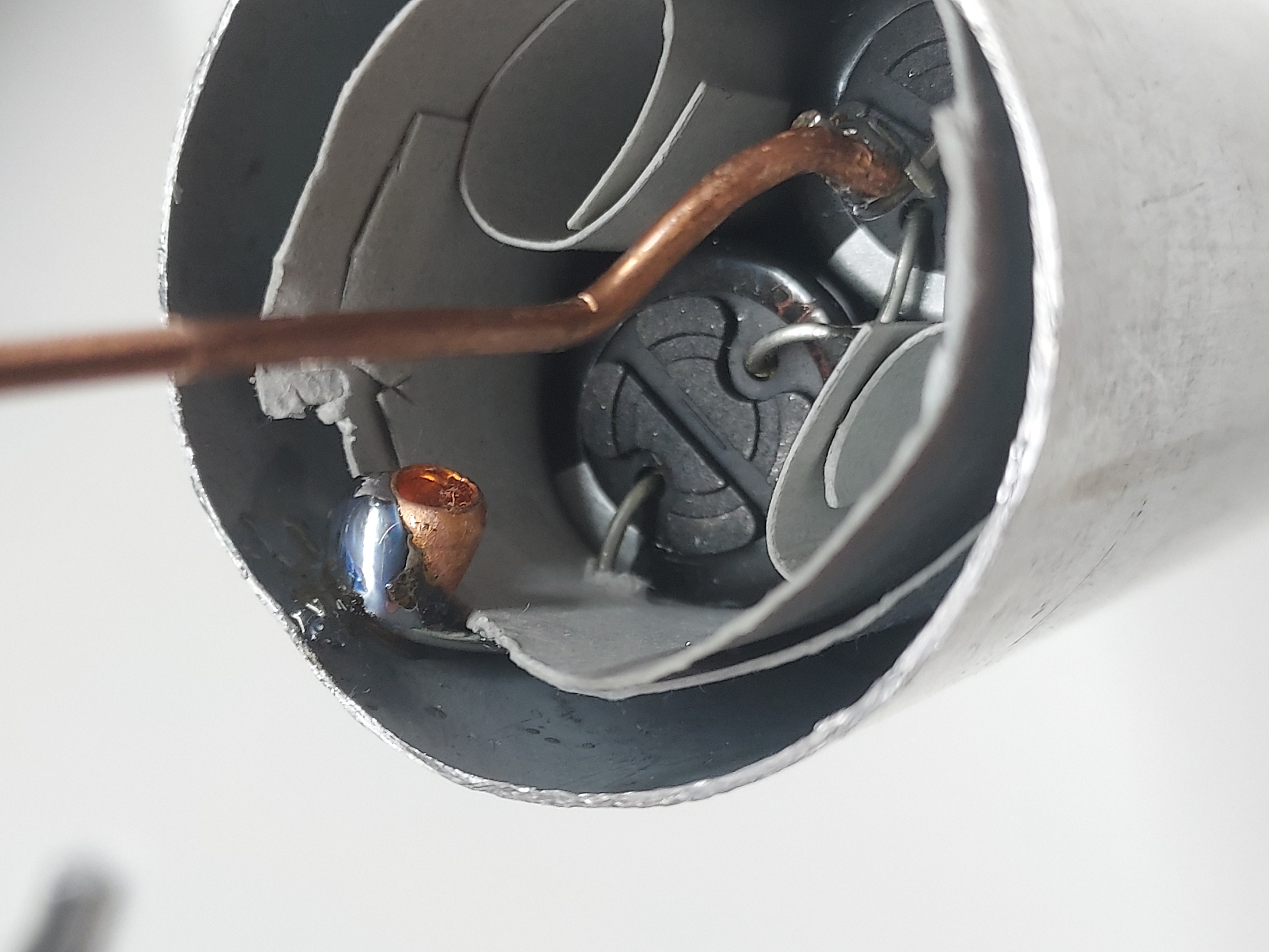
This cap is now ready for epoxying the bottom back to it.
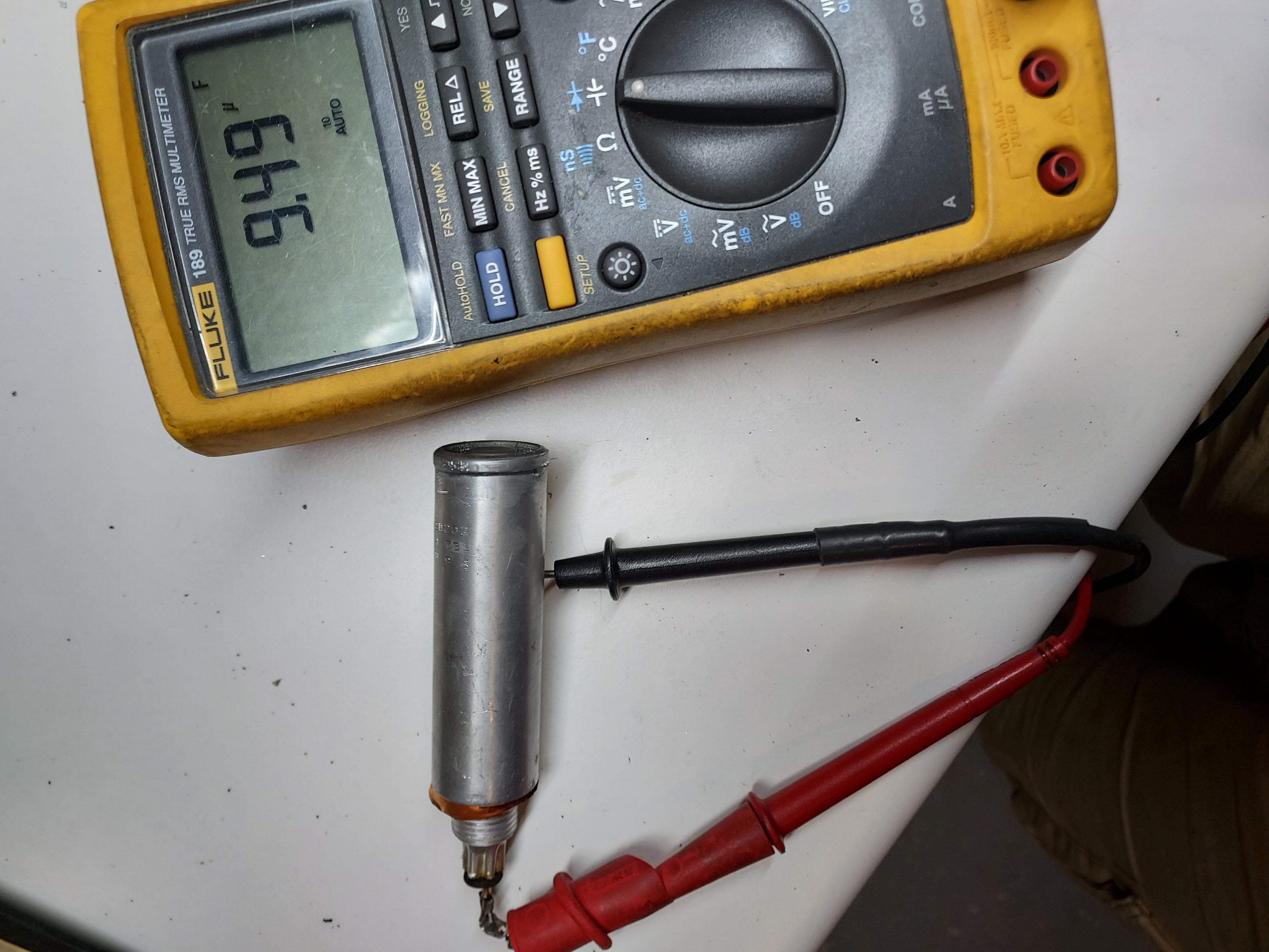
Now the 4uF cap. This is the second filter cap, and it could be larger than the original, so I use a high ripple 10uF 450V cap (170mA). This cap does not experience lots of ripple as it is preceded by the inductance (Field coil), so for all I care, it could be just a GP electrolytic.
Unlike the first cap, which is insulated from the chassis, this one uses the shell as the GND, and so the bottom of the shell could benefit from being solid, so the most natural place to cut is the cap's groove at the top.
Now I had to think of how to best connect the minus of the cap to the shell, so what I did was manufacturing a copper foil ring with a solder terminal, which would receive the inner cap's negative through a hole in the shell, while itself being between the shell's bottom and the chassis.
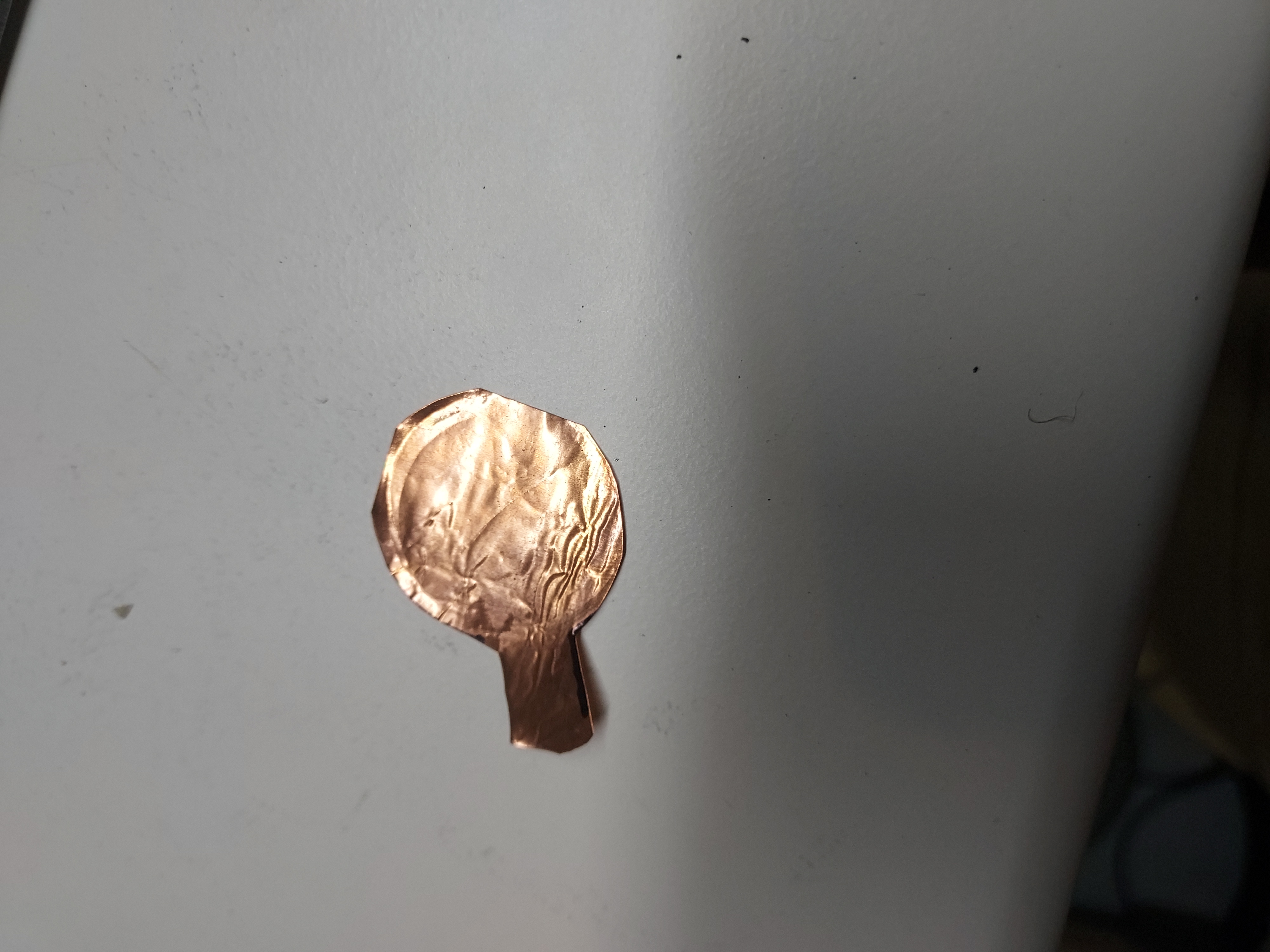
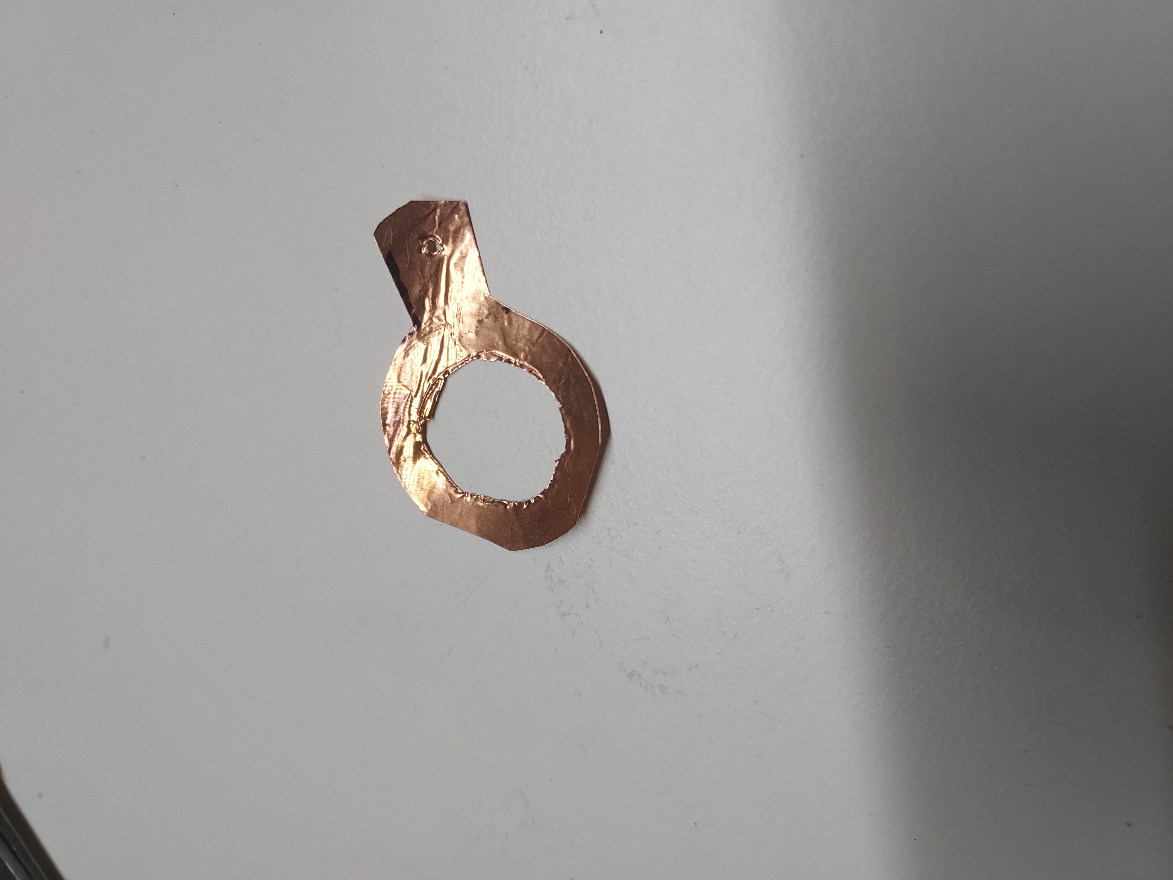
I soldered tug wires to the cap, to pull the leads through.
Then I trimmed and soldered the side lead.
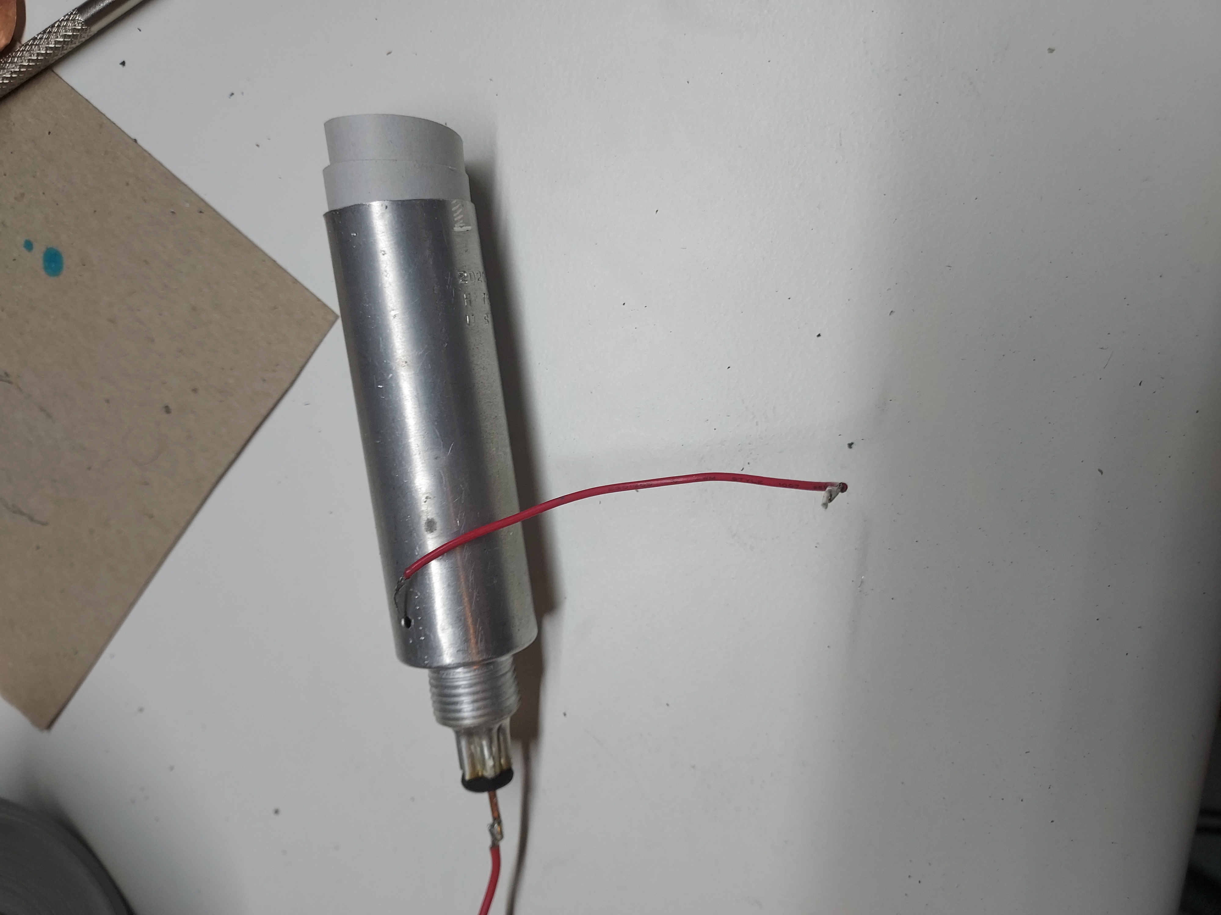
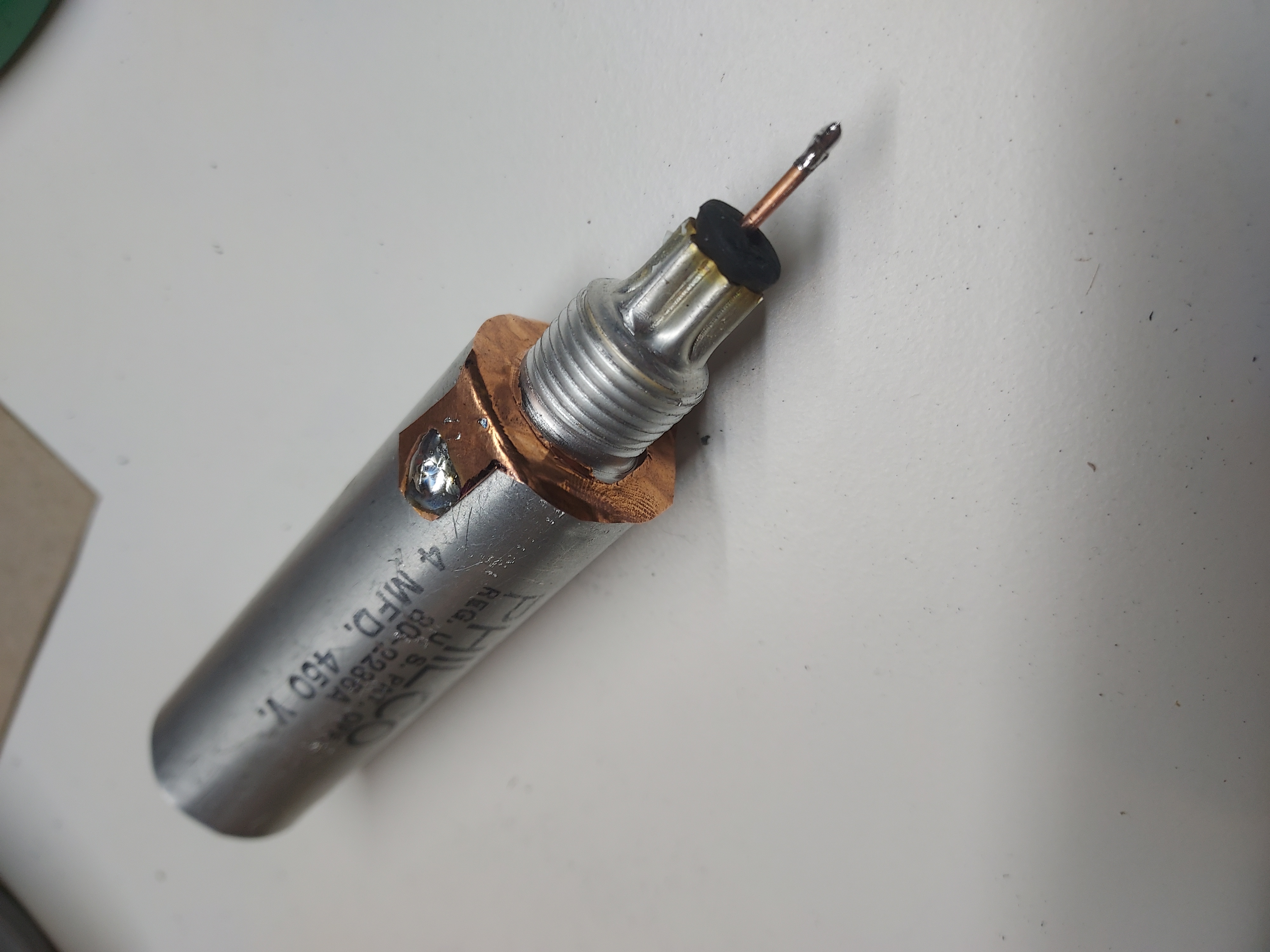
Then I measured the capacitance.
This is how the caps look in citu, and the whole chassis after I also changed some broken antenna/GND wires.
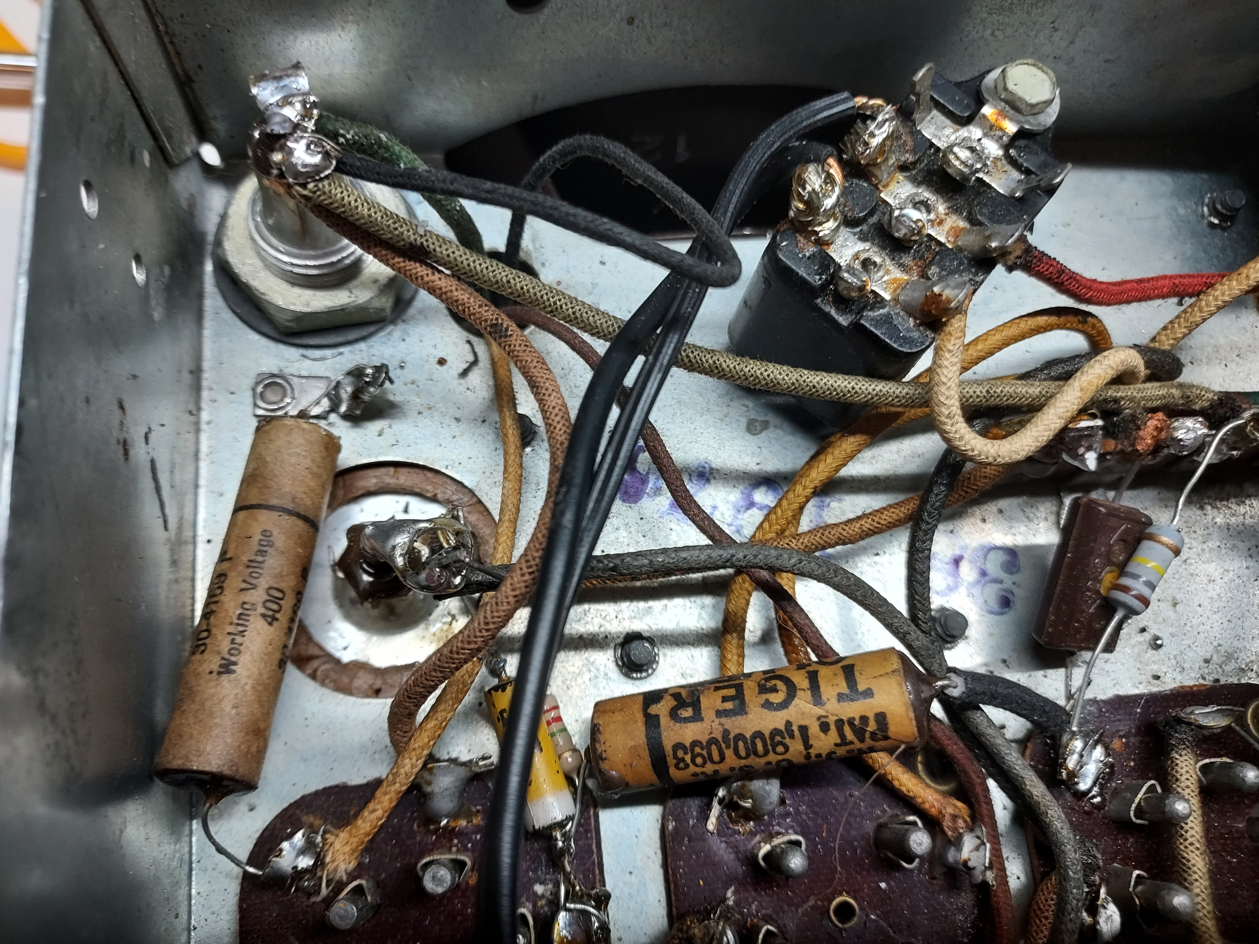
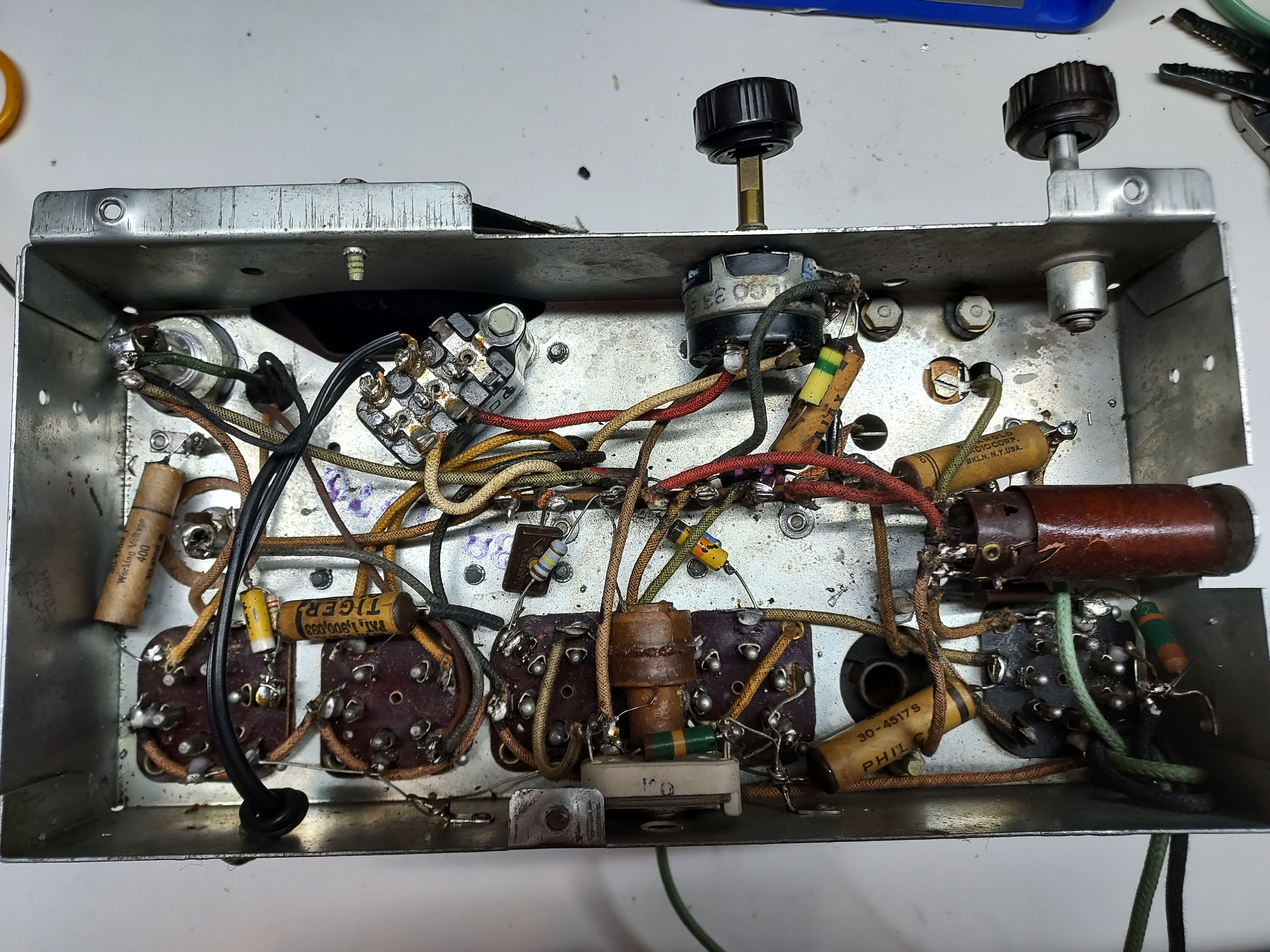
After this I pretty much just plugged it in 120V outlet and heard it receive. The voltages are very close to those shown at the chart, the rectified one is a bit higher (10V or so), because, well, it is today's Mains voltage, which is higher than 110V.
The alignment is pending.
People who do not drink, do not smoke, do not eat red meat will one day feel really stupid lying there and dying from nothing.
Posts: 1,151
Threads: 47
Joined: Feb 2015
City: Roseville, MN
Nice job Mike. "And nobody will be the wiser." (Stan Laurel) Would there be any issue with the dissimilar metal problem between the copper and aluminum?
Posts: 4,906
Threads: 54
Joined: Sep 2008
City: Sandwick, BC, CA
Mike;
Another method I thing may work to ground an electrolytic can would be to solder a lead to a large star or locking washer under the can, some makes used to do this from the factory, some will just pinch a wire underneath the can itself, and hope for the best. I had not thought of using a copper rivet through the can though, that was a good idea, if you can find the correct flux you can solder to aluminum, but how long it will last is a guess.
Regards
Arran
Posts: 16,533
Threads: 573
Joined: Oct 2011
City: Jackson
State, Province, Country: NJ
Rod
Indeed, copper and aluminum do form a galvanic couple, whicb some consider the worst.
However that requires some moisture, and in well-controlled climate this should not be much of a problem.
Arran
Yes, and I did that once before, forgot in which radio from those I restored. That was early on. I just wanted to keep wires from sticking out from the can.
Another way would be using two wires out of the cap, as in some Philcos. I probably could've gone for that too.
The small cap was somewhat inconvenient. If you cut close to the base, you can't tork it when handling, plus it will be obvious; if high, it looks nicer (if really diligent, it could look very nice), but the aspect ratio interferes with handling the cap inside easily.
As for the flux, yes there are tinning fluxes for aluminum. They even claim those are not very corrosive.
Thinking of it, the flux has to get rid of Al2O3, which is corundum..... 
I am not sure I want to deal with chemicals like that; the contents of the electrolytic caps of unknown composition are enough for me at this point. 
I thought of alignment tonight, but it will take a bit of time, and today is a heat wave, and I want to jump in the pool, and then I need to call mom.
Maybe Friday.
People who do not drink, do not smoke, do not eat red meat will one day feel really stupid lying there and dying from nothing.
Posts: 16,533
Threads: 573
Joined: Oct 2011
City: Jackson
State, Province, Country: NJ
Before proceeding with alignment, I remembetred the grommets for the tuning cap had to be changed.
They were fully flattened and crumbling.
It was easy to extract them, but 38-12, at least this version (this tuning cap has the threaded posts close to each othere; there is another version where they are much farther apart) does not make it easy to put the new grommets back. The reason being, the metal ferrules, that go inside the grommet, cannot be easily pulled out (they are mushrrom type, with the wide end facing up) due to the fact that the tuning cap assembly is bound to the tuning shaft, that is mount to the chassis, and so the cap cannot be extracted or, at least, pulled far, without undoing the tuning string routing, which then would require some extra skill to put back.
I took a shortcut: I used some small grommets, that many years ago I cut in half, to push under the ferrules, having pulled the cap just enough so the spaces around those metal ferrules would be sufficient for the grommet to go around that ferrule. Then the other half goes from teh chassis side, and then the washer and the nut. The ferrule dictates the height of the cap, so there is no concern about the height of the dial to change.
I will go now and attempt that alignment after all.
People who do not drink, do not smoke, do not eat red meat will one day feel really stupid lying there and dying from nothing.
Posts: 16,533
Threads: 573
Joined: Oct 2011
City: Jackson
State, Province, Country: NJ
Have just finished the alignment and shot a short video of the radio receiving with a short 7-ft wire in the basement of my house.
The reception is fine.
The radio was aligned previously and was reasonably close to being aligned. I followed the instruction for initial setting of the pointer, which has to be 1/16" below the three-line frame top, and this is what II had to compensate (mostly) when adjusting the padders: the needle was previously set exactly at the lower end of the dial.
This is the link to the video of it receiving.
https://m.youtube.com/watch?v=CF2AzpNNrn...e=youtu.be
People who do not drink, do not smoke, do not eat red meat will one day feel really stupid lying there and dying from nothing.
Posts: 1,883
Threads: 120
Joined: May 2008
City: Omak
State, Province, Country: WA
Hello morzh,
Nice on the re-stuffing of the Electrolytic capacitor can .
See the great posts I miss being away from the forum .
Sincerely Richard
Users browsing this thread: 1 Guest(s)
|
|
Recent Posts
|
|
1949 Motorola 5A9M
|
| This would be the second portable in the "other radios" forum where I have a similar one in my collection. I h...Arran — 12:41 AM |
|
Looking for any info: 1977 Ford-Philco Console Hi-Fi Turntable and Radio
|
| Hi PittsburgTost.
The record changer looks like a Garrard or BSR (Likely Garrard). The spindles just pull out and pu...MrFixr55 — 11:57 PM |
|
Looking for any info: 1977 Ford-Philco Console Hi-Fi Turntable and Radio
|
| Hello PittsburghToast ,
Welcome aboard and it looks like gary may have something for you !
now if I dig through my se...radiorich — 11:35 PM |
|
Model 80 Antenna Issue?
|
| You are kind of on the right path. You can touch the grid cap of the Detector/Oscillator 36 tube. I'm expecting a respon...RodB — 08:48 PM |
|
Looking for any info: 1977 Ford-Philco Console Hi-Fi Turntable and Radio
|
| Welcome to the Phorum, PittsburghToast! I found an old thread that my interest you regarding the quality and worth of P...GarySP — 08:48 PM |
|
Looking for any info: 1977 Ford-Philco Console Hi-Fi Turntable and Radio
|
| Welcome to the Phorum!
:wave:
We do not have anything on that unit in our digital library. There is a Sam's Photof...klondike98 — 08:47 PM |
|
Model 80 Antenna Issue?
|
|
I’ve replaced all the caps and resistors and the radio is working but minimal volume unless I put my hand near the re...Hamilton — 08:24 PM |
|
Looking for any info: 1977 Ford-Philco Console Hi-Fi Turntable and Radio
|
| Hi there! this is my first time posting. I recently picked up this Ford-Philco Console record player and radio at a yard...PittsburghToast — 07:28 PM |
|
philco predicta
|
| I found that where I have the 140v B+ there is 50v and the tuner receives 235v through the orange cablecgl18 — 04:14 PM |
|
Philco 91 code 221
|
| Chassis grounds thru rivets is another good place to look. Oh and the stator screws on the tuning cap where the leads at...Radioroslyn — 08:11 AM |
|
Who's Online
|
| There are currently no members online. |

|
 
|


![[-] [-]](https://philcoradio.com/phorum/images/bootbb/collapse.png)


