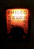
I am working on replacing the rubber wires for the station indicator lamps, and I have a tan-ish coloured wire that runs out of the chassis in the same location as the wires for the dial lamps. But the wire has been cut and tied around the indicator lamp harness. I was able to trace the wire back to the band switch.
Where is this wire supposed to connect?
I tried looking at pictures of other chassis, but none show a close up of that area.
It appears to me that the wire is attached to A1 of the bandswitch which has 6.3 volts on it for the lamps. Maybe it is for an external lamp somewhere else on the chassis. Can you determine if that switch wafer is wafer A or is it wafer D? That looks like a 10k resistor next to the wire but I can't find a 10k connecting to the bandswitch.
Oddly enough I have a Canadian Philco service book for 1939, and it has the 39-3116 in it, I didn't really study it in detain but I believe it's pretty much the same as a 39-116 but with less rubber/gutta percha covered wire. I will have to look for the book and see what it shows, but my first thought is that if that wire is connected to the band switch that maybe it's to indicate what band the set is on? Are the mystery control circuits on these always on standby or do you have to turn them on manually?
Regards
Arran
(This post was last modified: 11-20-2025, 10:28 PM by Arran.)
Modified 11/21/25, 8:27 ET, from the original post for more clarity than I could deliver at midnight when I was suffering from a bout of insomnia:
OK, I'm gonna hazard a guess. I am looking at the 39-116 schematic from our website. My guestimate is only valid if there is no difference between the 39-116 and the 39-3116 when it comes to this circuit.
Here is a rather neat video on the 39-116, in what I think to be a very handsome cabinet:
Based on your picture, and the schematic for the 39-116, available on our Philco Library picture, if the wafer shown is "A", then I think that the wire connects to A1 of the A wafer of the band switch. If the device on the next terminal is a resistor of low resistance, say 10 Ohm and if that terminal is A3, then the resistor is fed by the 6V filament winding of the power transformer, and when the band switch is in the "preset" position, and supplies this wire, a common power feed to a series of indicator lights indicating what station is selected by the Mystery Control stepper when the preset function is selected by the band switch. The desired light is selected by one of the stepper switch wafers, #81 on the schematic #81 is a compound stepper switch which selects the oscillator coil, antenna capacitor and indicator light.
If these indicator lights are missing, this may be the reason for the wire being tied back to the harness for what is apparently the speaker. If these indicator lights are missing, then you can merely cut the wire; it will not affect general operation of the radio.
Hope this helps.
"Do Justly, love Mercy and walk humbly with your God"- Micah 6:8
"Let us begin to do good"- St. Francis
Yes, this is the Canadian version of the 39-116. Minor differences in the way the set is built, mainly parts used (my estimate- 80% Canuck, 20% Yankee parts)
The parts built in Canada seem to all have cloth covered wire vs the U.S. parts which have the rubber covered wire. I'm glad that most of the wire used is cloth!
Thanks for the diagnostic help. Yes, the wire IS for the power for the preset station selector lights. Someone has snipped it off, and rerouted it through the chassis, bringing the wire out the top by the dial where the lamp wires come out. That's what confused me! Why didn't they just disconnect it under the chassis? The wire covering to the lamps is severely degraded, and so I assume that something shorted out, hence being disconnected. But by disconnecting and re-routing it the way they did...the wire was still live! And the covering on it isn't any better than the lamp wire.
Now I need to find one of these, I had an opportunity to get one of t's non mystery control brothers, but I have a mystery control I should put to use. I have a few sets like this where someone was playing around under the chassis, typically things like adding phono jacks, external speaker connections, probably the worst one was a Rogers 10-12 I have where someone rewired the audio amp section from a class A-B power output, similar to a Philco 118, into just a class A push-pull setup.
Regards
Arran
I think that the cabinet of the 39-116 is absolutely gorgeous as compared to the regular console cabinets of the day. There is one of these in the "office" of the William Vanderbilt mansion museum in Centerport, NY.
I have long been a fan of adding aux inputs to period radios for diagnostic purposes and also to enjoy the sound of these radios without dealing with the distortion of current AM stations, noise and the performance of my home AM transmitter. Adding phono jacks was often done "in period", probably within 10 years of buying the radio. I'm sure that period electronics magazines for the electronics hobbyist (and back in the day, there were many) had articles for adding phono inputs, as RCA and others sold standalone turntables and changers meant to be plugged in to the radio. These got really popular in the 40s and 50s. RCA made a kit, P/N 9824 in the late 1930s to early 1940s to add a phono input. Several black dial Zenith schematics included instructions for adding radio-phono switches. I even remember an article in Popular Electronics in the 1950s where someone added a jack to plug an 8" speaker into his portable TV for better, front protected sound.
The important thing is to not do a hack job.
The idea of converting a class AB power amp to class A was interesting. Maybe the person was a HiFi and classical music affectionate and purist. Class B was popular in the early 1930s due to the high output wattage and circuit simplicity, but distortion was rather high. However, back in the day, RCA considered a distortion of under 5% to be "undistorted"
Factory installed Phono (or TV or FM) inputs became popular in the 40s and 50s, and even earlier. MY GE S-22A (RCA R7A), RCA 5T7 and RCA 5BT and 6BT farm sets and other sets of the early 1930s had terminal boards on the back to wire an external phono. The switch was part of the phono. I have 3 RCA sets from 1940-1948, including a 14BT2 1.4V / 90V farm set, a 16T2 and an RCA 1R91 "Livingston" I have 2 GE clock radios with factory installed RCA plugs and a very unique way of switching from radio to phono. The volume control had a center tap on the resistor to ground. One leg had the radio, the other leg had the phono jack. The wiper connected to the grid of the 1st AF through a cap. Other radios, especially Emerson, had an RCA Jack with a contact that was a switch arm. When a plug was inserted, the radio input was switched out, similar to an earphone or headphone jack on transistor sets.
"Do Justly, love Mercy and walk humbly with your God"- Micah 6:8
"Let us begin to do good"- St. Francis
Mr Fix;
I think that the alterations to the Rogers were done possibly for expediency, from what I can tell the driver transformer failed, and rather then sourcing a replacement from Hammond, whomever worked on the set just rewired the triode connected 6F6s that were in class A-B, to a conventional class A setup. Unfortunately this wasn't the only thing they changed as they removed a coil acting as a 10 kc wave trap, some circuitry related to the tone control, which was mounted on a circuit/terminal board, and moved one of the tube sockets for some reason. I wish I had know this when I bought the set, but it looked really good from the top side, the only thing obvious was that the power supply, which is offboard in the bottom of the cabinet, had it's filter caps replaced, and lock wired on. I haven't really done any work to it other then cleaning the dust out, and will probably have a go at it after I overhaul the Canadian Majestic "Marquette" which has similar circuitry in the front end, including variable IF bandwidth https://www.radiomuseum.org/r/rogerstube...ch_60.html The set linked to is not mine, but it gives you the idea, it only has 7 tubes as opposed to the 12 that the 10-12 has.
Regards
Arran