12-27-2013, 11:29 PM
Ive been working on a nice, original 19B Code 123 and have run into troubles.
http://www.philcoradio.com/tech/images/19v5.jpg
I have a thread going on ARF and hope to get some input from "the Philco Experts".
From what I have seen, the radio was never previously worked on. All components, including the two electrolytic cans, are original. I re-stuffed the electrolytics, checked the tubes, and tried the set. I got nothing but a low steady hum that is controllable with the volume control. I went ahead and replaced all the caps in the blocks and checked the resistors. Still no reception at all-nothing. I have not yet replaced the caps in the tone control as it looks like it will require some disassembly. I also have not checked the shadow meter coil.
I checked tube socket voltages and Im only seeing 100v on the 36 oscillator plate. Other voltages seem reasonable. Im not the greatest at checking coils, but im finding "sets" of pins on the Antenna, detector, and oscillator coils that add up to close to what the schematic says. 2nd IF looks good as well. Antenna post to chassis ground = 27 ohms.
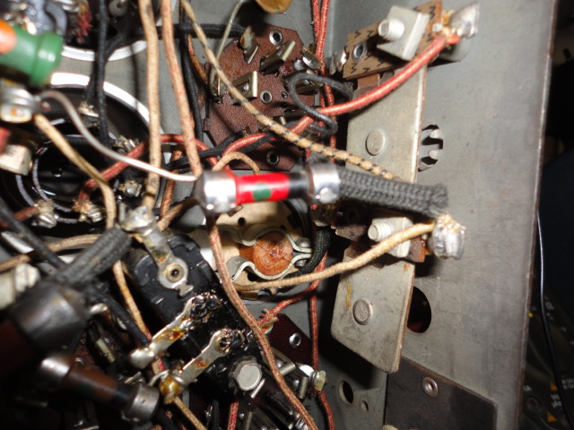
However, I cannot find the secondary winding on the 1st IF transformer. There are two compensating capacitor trimmers on the back wall of the chassis.
Measuring between the top and the bottom terminals of the IF primary yields 55 ohms- good. Measuring between top and bottom terminal of the IF secondary shows open/high resistance.
My questions are:
Is this a reasonably accurate way of checking the two 1st IF trans windings, and if so, does it in fact indicate an open 1st IF secondary?
Would this account for the low 36 plate voltage?
Could the old tone control caps or shadow meter coil shut down all reception if defective?


![[-] [-]](https://philcoradio.com/phorum/images/bootbb/collapse.png)


