Posts: 2
Threads: 1
Joined: May 2014
City: Maine
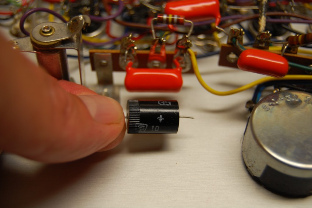
I'm restoring a 1976 Mercury 204 "Drugstore" tube tester. I have a schematic which may be from an earlier model and shows a diode in the circuit where I found this component If this is a diode, I've never seen one like this. Does anyone have any ideas? It tested 1.8M ohm in one direction and 900K ohm in the other direction.
Thanks for any help.
Jim


Posts: 16,533
Threads: 573
Joined: Oct 2011
City: Jackson
State, Province, Country: NJ
I think it could be a selenium rectifier (yes a diode of a sort).
Plus sign usually denotes the positive out, not the P junction side as in diodes (which would be the negative out).
Posts: 2,573
Threads: 337
Joined: Jun 2013
City: lawrenceville nj
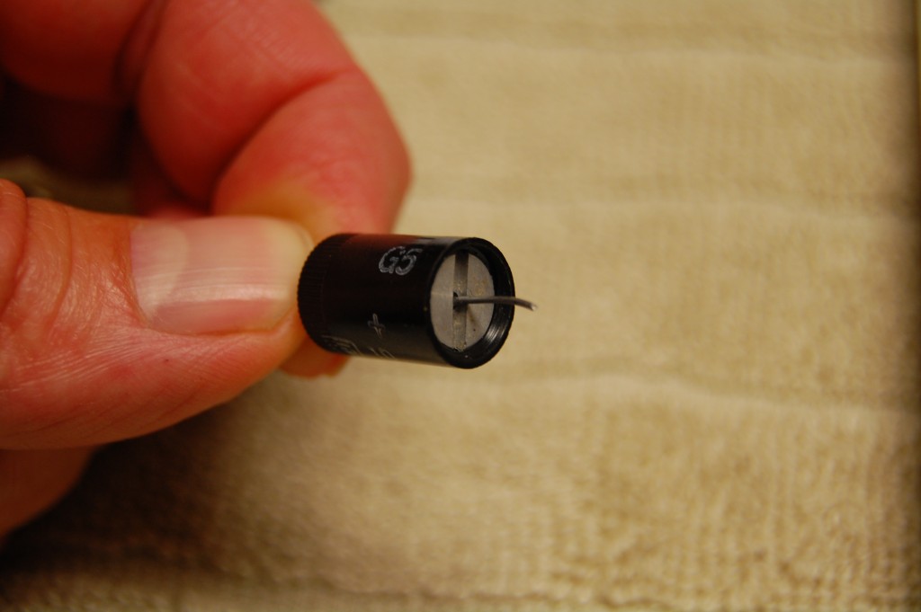
whats other side of disc look
Posts: 411
Threads: 42
Joined: Sep 2008
City: Ironton Ohio
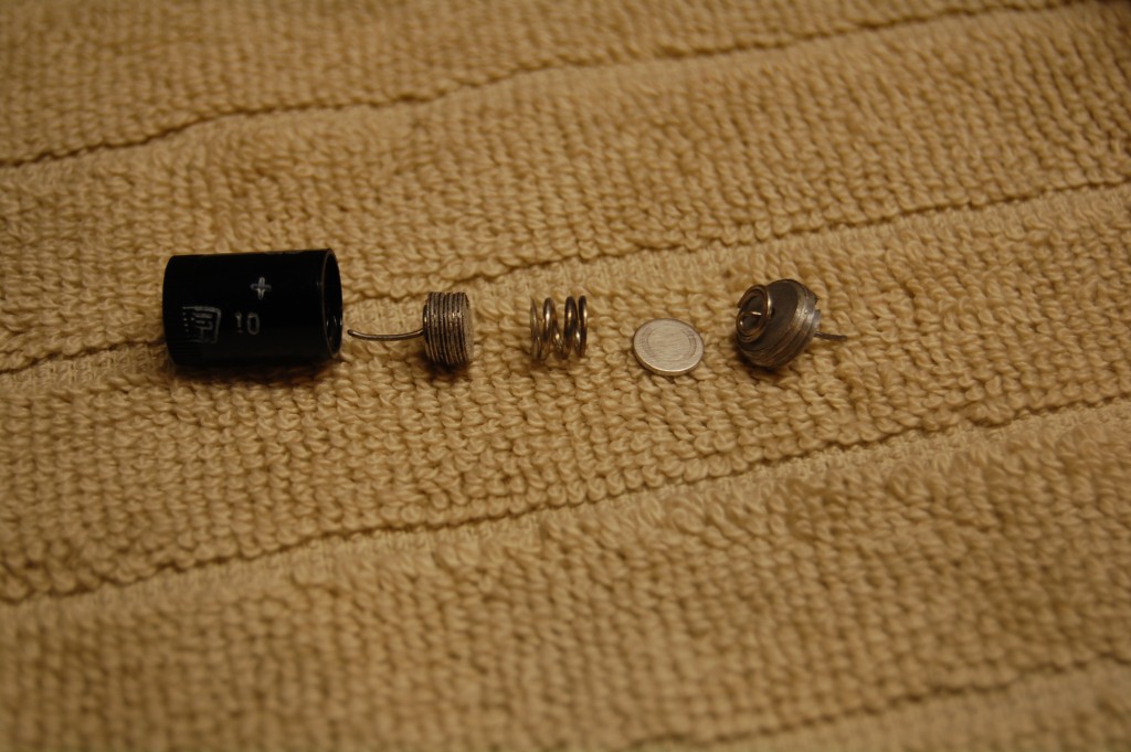
Since it comes apart, I believe it is a button cell battery assembly. Are there any bias voltage symbols in that part of the schematic? Some of the old bias cell symbols look like a modern diode symbol except it should have a + and - on either end.
(This post was last modified: 09-02-2014, 01:28 AM by
tab10672.)
Posts: 2,573
Threads: 337
Joined: Jun 2013
City: lawrenceville nj
that's what I was thinking tab but didn`t what to be ridiculed for saying it looked like a battery in tube radio
Posts: 411
Threads: 42
Joined: Sep 2008
City: Ironton Ohio
I was shocked to find one in a 37-602 philco. I didn't even know they made batteries that small in 1937 let alone use them in a tube type electronics. Although it looks different than modern button cells (acorn shaped) it is about the same diameter as a watch batt.
(This post was last modified: 09-02-2014, 01:14 PM by
tab10672.)
Posts: 2
Threads: 1
Joined: May 2014
City: Maine
I've found out that it's a copper oxide rectifier and that they rarely go bad, so I'll put it back together carefully and reinstall.
Thanks for the suggestions.
Jim
Posts: 411
Threads: 42
Joined: Sep 2008
City: Ironton Ohio
Never heard of those before, learn something new every day. Since they "rarely go bad" it's strange that it would be in an easy access/replaceable assembly.
Posts: 1,703
Threads: 55
Joined: Sep 2005
City: Evanston, IL
The copper oxide alloy is not solderable, hence the spring/clip type connections. Be sure you put the "disc" back in the way it came out
so it matches the polarity marking. ;)
Chuck
Posts: 16,533
Threads: 573
Joined: Oct 2011
City: Jackson
State, Province, Country: NJ
The selenium elements were not solderable either, they came as bolted assembles with solder lugs,
https://en.m.wikipedia.org/wiki/Selenium_rectifier
or in flat boxes with compartmentalized inside plastic spring loaded holders, that held serialized elements.
http://www.bakersfieldads.net/Algoso-/E2...50C250.JSP
http://oldradio.onego.ru/COMPS/selen_abc.jpg


![[-] [-]](https://philcoradio.com/phorum/images/bootbb/collapse.png)


