Posts: 10
Threads: 5
Joined: Sep 2015
City: Dayton, Ohio
Newbie to the phorum here...first post.
I am in the process of restoring a Philco 610B radio that was already working, but never had the caps and several other items changed from when I purchased it at a "radio" shop in New Hampshire about 10 years ago. The shop made some small repairs at the time to get it running, but no real restoration was done on it. Though I am not sure if it was this shop, but at least one item was added that was probably all that was available at the time - a .5 mf 600 volt capacitor which is in one of the photos attached. It is not in the original schematic and I am wondering if I should include it in the restore or go with the original schematic. My electronic theory knowledge is not good enough to know why it might have been added, and any comments regarding that would be appreciated.
First, the snippet of the schematic with my notations:
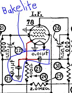
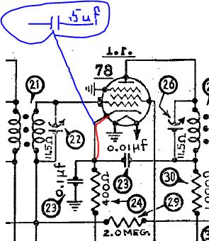
Here is the capacitor that was put into the circuit, as best as I can tell between the cathode of the 78 tube and the bakelite containing the .1/.01 capacitors:
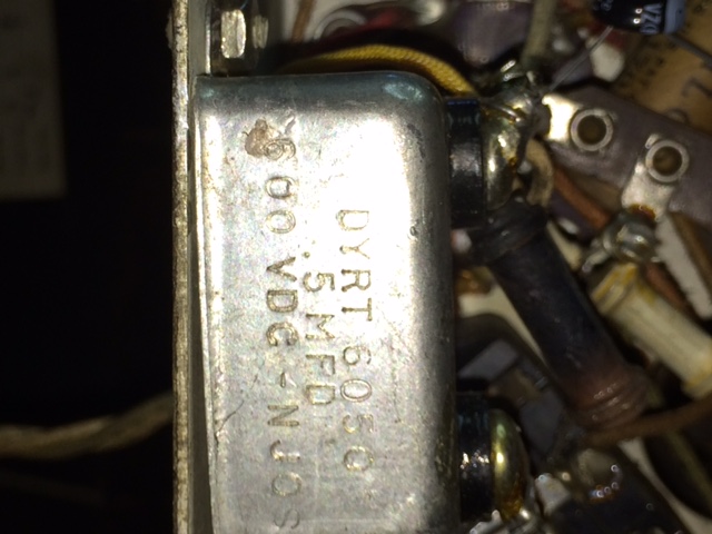
Here are two shots of where the capacitor is wired:
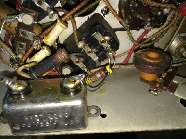
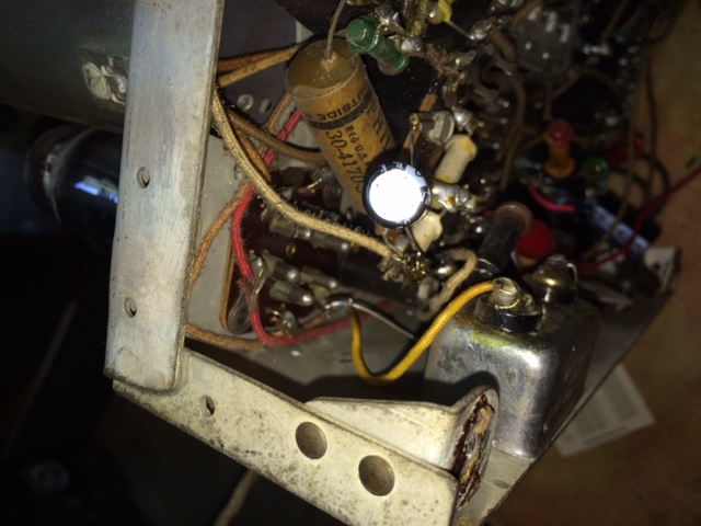
Posts: 7,305
Threads: 270
Joined: Dec 2009
City: Roslyn Pa
Hi and welcome to the Phorum!
Your .5 @600v is the cathode bypass cap for the IF amp. Value is not real critical but should be .1 or bigger. Voltage wise 600 is way overkill as there is probalby less than 5-10vdc there. Would just rebuild block cap w/original values.
Terry
Posts: 5,203
Threads: 276
Joined: Nov 2012
City: Wilsonville
State, Province, Country: OR
Welcome to the Phorum!! 
Rebuilding the bakelite block caps is not hard. Here's a tutorial.
Posts: 10
Threads: 5
Joined: Sep 2015
City: Dayton, Ohio
(09-05-2015, 01:48 PM)Radioroslyn Wrote: Hi and welcome to the Phorum!
Your .5 @600v is the cathode bypass cap for the IF amp. Value is not real critical but should be .1 or bigger. Voltage wise 600 is way overkill as there is probalby less than 5-10vdc there. Would just rebuild block cap w/original values.
Terry
Thanks to both of you for the response. I just want to make sure I made myself clear by double-checking the responses. I am aware of the bakelite, which contains the two .1 mf and .01 mf, but what is not in the schematic is the .5 mf 600 v DYRT paper capacitor enclosed in the silver box in the original photo. I don't see it in the schematic at all. See attached to this reply how the .5 was added to the circuit at the point where I have the blue lined jumping off point drawn. Is that what you referred to in your response, Terry? I have already rebuilt the bakelites, Bob, as I have done that before. I circled the .1 and .01 and marked it bakelite to let you know that is what it was. I wasn't actually referring to it as much as that DYRT .5 addition. Terry, if it is an IF cathode bypass, is this something that might have been added later by Philco on later versions of the 610?
Thanks for all patience and advice!
Jim
Posts: 5,203
Threads: 276
Joined: Nov 2012
City: Wilsonville
State, Province, Country: OR
Here's a possibility. If the original 0.1 was shorted, the added 0.5 was a replacement of higher capacitance, for the 0.1. I would simply remove it from the radio.
Posts: 10
Threads: 5
Joined: Sep 2015
City: Dayton, Ohio
(09-05-2015, 06:26 PM)klondike98 Wrote: Here's a possibility. If the original 0.1 was shorted, the added 0.5 was a replacement of higher capacitance, for the 0.1. I would simply remove it from the radio.
Just to update on this 610B circuit. I tried removing that DYRT .5 capacitor and the tuning was highly affected. I no longer received any stations, just a little heterodyning sound as I tuned around. I put it back in and all worked again.
So I removed it and put in a newer .5 mf, 600 v capacitor I had on hand. It seems the sound and station reception is much better than even when that old DYRT was in there. It was possibly wearing out - I don't have a capacitor tester - but things have improved with the reception.
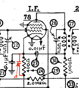
Essentially, there is the .5 uf in parallel circuit to the 400 ohm resister that doesn't seem to be in the original circuit. Odd that it worked at one time according to the schematic without that capacitor.
Addition is in orange.
Jim
Posts: 1,824
Threads: 114
Joined: Jul 2014
City: Sneedville, TN
The way you have the .5 drawn there in the last illustration shows it is being used as a substitute for the .1 labeled as #23, as a bypass condenser on the 400ohm R24. I would imagine changing the .1 in the block to a .5 would have much the same effect, also, it should work fine with the original values. Make sure the grounding of that .1 is good, that could be part of the problem.
Posts: 10
Threads: 5
Joined: Sep 2015
City: Dayton, Ohio
(09-06-2015, 12:33 AM)mikethedruid Wrote: The way you have the .5 drawn there in the last illustration shows it is being used as a substitute for the .1 labeled as #23, as a bypass condenser on the 400ohm R24. I would imagine changing the .1 in the block to a .5 would have much the same effect, also, it should work fine with the original values. Make sure the grounding of that .1 is good, that could be part of the problem.
Thanks, Mike. I'll be updating that bakelite when I get my parts on order sent to me. I'll temporarily remove the .5, tack in the .1 and see if anything changes. The person who made previous repairs to this radio before I bought it simply installed that .5 DYRT that I removed. As you mention, perhaps he was just fixing a problem without having to mess with the bakelite and used what he had on-hand.
Jim
Users browsing this thread:
|
|
Recent Posts
|
|
1949 Motorola 5A9M
|
| Nice job on the battery, Bob. Can the box be opened to replace the 9 volters?RodB — 11:32 AM |
|
Philco 46-1209 strange behavior
|
| Thank you for the detailed response MrFixr.
To clarify, the hum starts when the tubes are fully warmed up, and goes a...sq65 — 09:15 AM |
|
Philco 46-1209 strange behavior
|
| MrFixr
The chassis, if there is no ground pin in the AC plug, due to the Y-caps from L/N to the chassis, is at 60VAC re...morzh — 08:47 AM |
|
schematics
|
| thanks I'll try the polar caps seperatelymseno — 07:38 AM |
|
Philco 46-1209 strange behavior
|
| Hi SQ55,
A strange issue indeed! Just so I have you straight, on a dim bulb you get normal operation after the set warm...MrFixr55 — 12:44 AM |
|
schematics
|
| I think mseno is talking about cap# 27 which is a multisection but in a paper tube. In cases like that I've usually be ...klondike98 — 11:25 PM |
|
schematics
|
|
Ohrenet :roll:
For their price I would chase a fly in a field. :twisted:Vlad95 — 11:21 PM |
|
1949 Motorola 5A9M
|
| A bit more work on the Motorola. I got the repro battery together right up until I realized the snap clips on the top o...klondike98 — 10:45 PM |
|
schematics
|
| Often restuffed.
If a twistlock, Hayseed Hamfest makes modern replacements.
morzh — 09:18 PM |
|
schematics
|
| Looking for a multi-sectional 8+16 mfd cap. Can't find any suppliers that carry it.mseno — 08:45 PM |
|
Who's Online
|
There are currently 1233 online users. [Complete List]
» 2 Member(s) | 1231 Guest(s)
|
|
|

|
 
|


![[-] [-]](https://philcoradio.com/phorum/images/bootbb/collapse.png)


