Thread Rating:
  • 0 Vote(s) - 0 Average
  • 1
  • 2
  • 3
  • 4
  • 5

GM model 120A ser. 7247A (power resistor)
#1

Hello, I have recently acquired a GM model 120A "The Hepplewhite". Did some cleaning and replacing bypass caps in the metal cans and checking the power resistor/voltage divider found it has an open in the 1st, 3rd and 4th resistors, see the attached photos. Does any one know the values of these resistors?
In the drawing of the voltage divider the 2nd is 60 ohm and the 5th is 450 ohm. One might guess by looking at the spacing of the tabs that the narrow spaced tabs would be the lower values and as the spacing gets wider the resistance would be higher, just a thought. If anyone has some suggestions for the open resistor values it would be greatly appreciated, I only have a couple 10W resistors to work with. I would like to purchase a variety of resistors to keep and at least come close to the values needed to fix this radio.
Thanks, Steve    
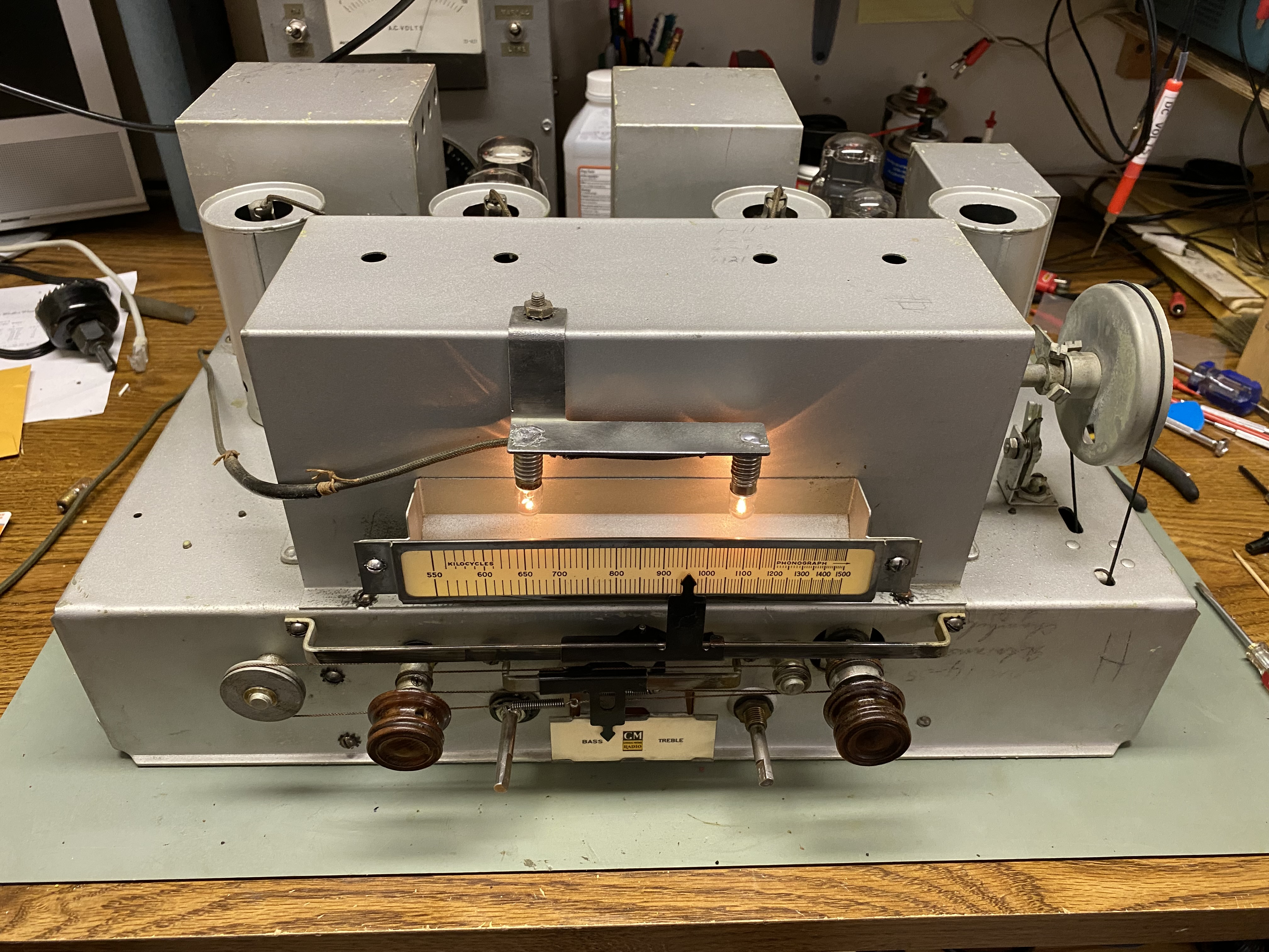

Attached Files Image(s)
       
#2

Unable to answer your question the only info I could find was from Beitmans and a link to Nostalgia air. Sorry I could not be of more help. David     http://www.nostalgiaair.org/Resources/915/M0039915.htm    
#3

Hello Steve,
That is very funny Because I know of another guy including myself who has a radio with this chassis ,
My General motors model 160 that  is called the Georgian Style .
The values of that resistor is different among some the models  anyway my resistor was also open but one the other members gave me these values .

Sincerely Richard


Attached Files Image(s)
   
#4

Hello Steve,
hopefully that helps you anyway mine came with a turntable too .
I still need to get my speaker fixed .

Sincerely Richard
#5

Hi Richard,
Thanks for the quick response, those values give me a place to start. I'm going to guess the ground connection is between the 4.8k and 59. I really like the looks of the Gregorian that you have mine is so plain looking in comparison but glad to own it non the less.
Excited to get it working again, will try to post updates.

Thanks again, Steve
#6

Hello Steve,
Craziest thig was there was another model for sale like a year after i bought mine in the same small town
yes that is where the ground is .

Can't wait to see more on your far as update and progress !

Sincerely Richard


Users browsing this thread: 1 Guest(s)
[-]
Recent Posts
Cannot Adjust an IF Transformer’s cores
Outstanding work indeed. I wish I could come up with solutions like this.slford310 — 11:16 PM
Cannot Adjust an IF Transformer’s cores
The abilities of our 'Phorum Pholks" never ceases to amaze me! Fantastic fabrication, Joseph! I'm waiting now for...GarySP — 08:27 PM
PT-6 antenna connections
Thanks. I never realized that was a notch noted in the schematic as described. I’ll recheck my wiring.bridkarl — 08:13 PM
Cannot Adjust an IF Transformer’s cores
Thank you! I was quite new to the Phorum when I started this post, so I feel like it might be advantageous to publish a ...jrblasde — 08:07 PM
PT-6 antenna connections
Notice in the schematic the notch at the bottom of the antenna coil is between pins 3 & 4. Yes, pin 6 of the 7C6 is...RodB — 07:34 PM
bridkarl
I have two PT-6 chassis. On both there is a blue wire that runs from the above chassis transformer to pin 6 of 7C6. So t...bridkarl — 07:23 PM
Cannot Adjust an IF Transformer’s cores
Joseph, now you are an engineer!!RodB — 06:37 PM
PT-6 antenna connections
Hi, reading your explanation I can see the confusion. If you take it one connection at a time it should result in a desi...RodB — 06:34 PM
Cannot Adjust an IF Transformer’s cores
It works! I received the PCBs this morning in the mail, and put everything together. I reused the base from the original...jrblasde — 04:32 PM
PT-6 antenna connections
I seem to have lost my way on this PT-6. I see the antenna aerial transformer schematic - I’m reading pins 1 through ...bridkarl — 12:30 PM

[-]
Who's Online
There are currently 3961 online users. [Complete List]
» 1 Member(s) | 3960 Guest(s)
Avatar

>