Twist Lock Style Solder Tabs
Posts: 287
Threads: 16
Joined: Jan 2024
City: Tulsa
State, Province, Country: Oklahoma
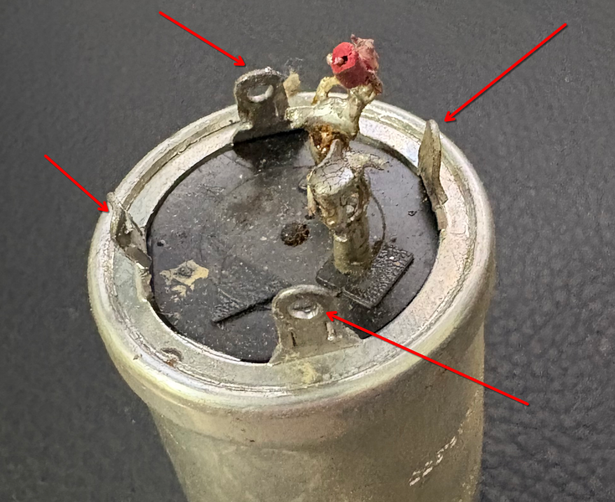
Does anyone know what you might call those solder tabs on vintage electrolytic capacitors? The kind of tabs that fit through slots on a chassis, and then you would twist them to structurally lock the capacitor in place while also electrically connecting to the chassis ground? I do not know what to search for in order to buy any connectors like this.

Joseph
Philco 46-480
Philco 49-906
Posts: 1,151
Threads: 47
Joined: Feb 2015
City: Roseville, MN
Are you referring to the phenolic wafer that they are sometimes mounted on? If so you would have to provide a diameter measurement.
Posts: 16,533
Threads: 573
Joined: Oct 2011
City: Jackson
State, Province, Country: NJ
They are called just that, twist-lock tabs.
They are not mount on the phenolic plate. They are always protrusions of a solderable metal ring that is pressed into the aluminum case.
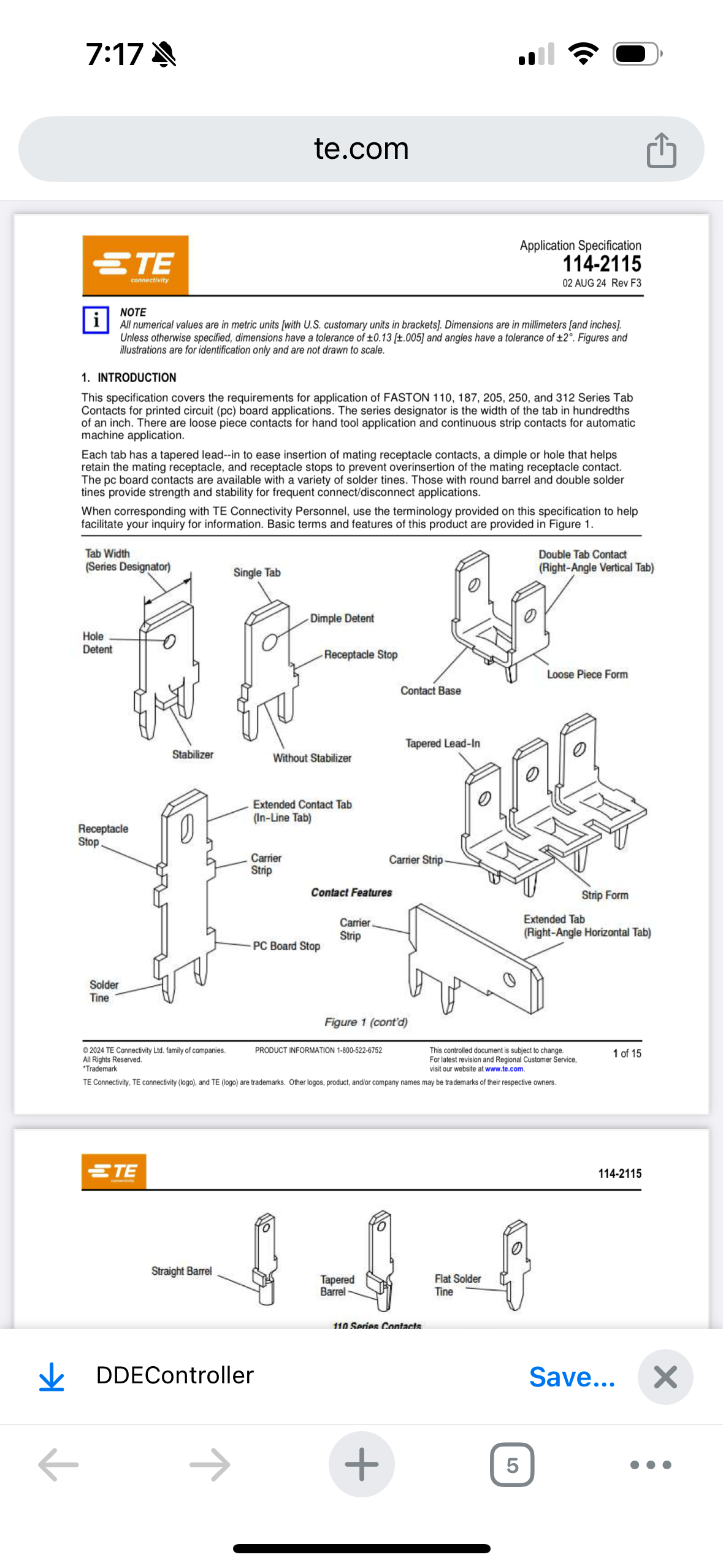
Now if you are trying to make somethfhing instead of them, by soldering them onto you PCB, well, you could just look for QC (quick connect) tabs, smaller gauge, and use them to solder to the PCB, and then put them through slots in tthat phenolic base and twist them. Or through slots in the chassis.
https://www.mouser.com/c/connectors/term...Disconnect
You can use these, and for twisting cut a notch on either side.
People who do not drink, do not smoke, do not eat red meat will one day feel really stupid lying there and dying from nothing.
Posts: 287
Threads: 16
Joined: Jan 2024
City: Tulsa
State, Province, Country: Oklahoma
No, not the wafer. I’m referring to the metal tabs on the capacitor itself which provide an electrical connection as well as holding the capacitor in place.
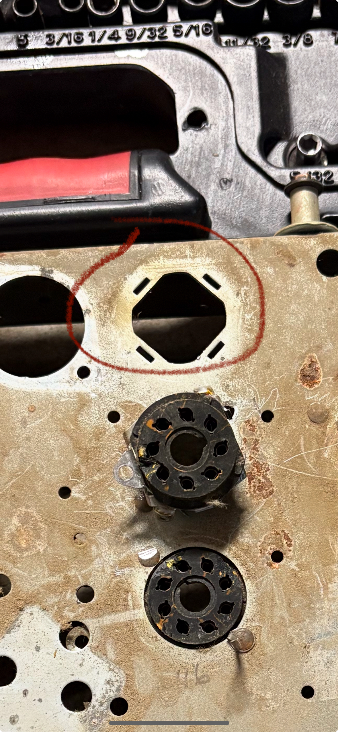
I’ve seen some capacitors with these tabs passing through slots on a phenolic wafer, and other times I’ve seen them pass through slots on the chassis itself. Here’s a photo of the chassis which this particular capacitor came from.

Joseph
Philco 46-480
Philco 49-906
Posts: 287
Threads: 16
Joined: Jan 2024
City: Tulsa
State, Province, Country: Oklahoma
Ah-ha, thank you Mike! Let me do a bit of research here. Yes, I’m trying to design a PCB substitute for that capacitor.
Joseph
Philco 46-480
Philco 49-906
Posts: 16,533
Threads: 573
Joined: Oct 2011
City: Jackson
State, Province, Country: NJ
Dunno if you saw it; you answered before I appended the link to that post.
This said, I successfully (and other folks too) disassembled and restuffed twistlock caps, at least 10 of them. If you carfull within reason, you simply reuse everything.
People who do not drink, do not smoke, do not eat red meat will one day feel really stupid lying there and dying from nothing.
Posts: 287
Threads: 16
Joined: Jan 2024
City: Tulsa
State, Province, Country: Oklahoma
These QC connectors are exactly what I am looking for. There are a range of useful styles.

Joseph
Philco 46-480
Philco 49-906
Posts: 287
Threads: 16
Joined: Jan 2024
City: Tulsa
State, Province, Country: Oklahoma
And thank you for adding the link. Yes, we are certainly posting responses back to back!
Joseph
Philco 46-480
Philco 49-906
Posts: 16,533
Threads: 573
Joined: Oct 2011
City: Jackson
State, Province, Country: NJ
If using solder-tine type, use flat, not round. This will make harder for it to spin in the solder hole.
People who do not drink, do not smoke, do not eat red meat will one day feel really stupid lying there and dying from nothing.
Posts: 287
Threads: 16
Joined: Jan 2024
City: Tulsa
State, Province, Country: Oklahoma
Great advice!
Joseph
Philco 46-480
Philco 49-906
Posts: 16,533
Threads: 573
Joined: Oct 2011
City: Jackson
State, Province, Country: NJ
Also, some of them are thin. You want some thicker one, as thin, when twisted, will not hold the cap tight. The idea is to get something reallhy close to the slot size. They should not twist easily, they should offer some resistance when twisted.
People who do not drink, do not smoke, do not eat red meat will one day feel really stupid lying there and dying from nothing.
Posts: 4,906
Threads: 54
Joined: Sep 2008
City: Sandwick, BC, CA
There is a sort P.C board substitute for twist lock cans called an "Adapt-a-cap", but I think that they are overpriced, and not really fit for purpose since they are using through hole solder pads on a P.C board for not only connecting the capacitors but connecting the wiring. I think that the method that Mike, and others use with restuffing the original can is more economical, and mechanically stronger then just tacking wires onto a disk of P.C board. It's like they didn't take into account that in vintage radios and TVs the base of these capacitor cans was also used as a terminal strip, not only for the capacitors but the ground lugs were used for other parts. If they really wanted to make the adapt a cap useful then instead of making it just a glorified P.C board they should make it like a terminal strip that fits over the hole in the chassis, but one in which you can put a can on top of to cover the radial lead electrolytics above the chassis. I don't think they even make one that fits in the way that one does on your Philco chassis, where the hole is punched to accept the ground tabs from the can, their are more like a copy of the diamond shaped mounting plates that would be riveted onto the chassis. They also have the same issue in that you have to remove the old can from the chassis, as you may or may not have to do with restuffing, along with disconnecting the wiring under the chassis.
Regards
Arran
(This post was last modified: 01-09-2025, 11:25 PM by Arran.)
Posts: 287
Threads: 16
Joined: Jan 2024
City: Tulsa
State, Province, Country: Oklahoma
Agreed, Arran.
I’ve got an idea in mind. I plan to design a PCB with the footprint of the old capacitor. I’ll solder the new caps into through-hole mounts on the PCB, and their pins will route to PCB mounted solder lugs for the wiring connections under the chassis. Finally, I’ll use some of these QC connectors for the twist lock connections to chassis ground. I feel that this design will be pretty robust.
I could restuff the existing caps, yes. However, I’m up to the challenge of engineering a modern-day solution. Challenge accepted!
Joseph
Philco 46-480
Philco 49-906
Posts: 1,883
Threads: 120
Joined: May 2008
City: Omak
State, Province, Country: WA
Hello joseph,
Sounds great I love using the autocad suite of software like the fusion 360 and tinkercad .
I have designed a few circuit boards and had PCB way make them for me .
Sincerely Richard
Posts: 4,906
Threads: 54
Joined: Sep 2008
City: Sandwick, BC, CA
Joseph;
I think that there may be a market for something like this, it would certainly be an improvement over those Adapt-a-cap things. Since I found out how much it costs to make something like those through an outfit like PCBway I don't know why anyone would pay $5 on up for one. Granted they are cheaper then a Heyseed Hamfest unit. but at least those are largely drop in replacements (I would like to know what capacitors they use inside good name brand or Chinese mystery brand?). One alternative I have also used was to mount a terminal strip under the chassis, on one of the lugs of the original can, or to one side of it, if there is room for it, leaving the original appearance above the chassis.
Regards
Arran
Users browsing this thread:
|
|
Recent Posts
|
|
Model 80 Antenna Issue?
|
| Thanks Gary and Rod.
I also found an article in the Philco Repair Bench under Service Hints and Tips, about installi...Hamilton — 12:32 PM |
|
Model 80 Antenna Issue?
|
| Hello Hamilton, here is a little information found in our Philco Radio Library at the bottom of the Home page. Hope it ...GarySP — 11:28 AM |
|
Model 80 Antenna Issue?
|
| I did as you suggested and touching the middle of the volume control did nothing so the coil has to be rewound. Any idea...Hamilton — 10:19 AM |
|
1949 Motorola 5A9M
|
| This would be the second portable in the "other radios" forum where I have a similar one in my collection. I h...Arran — 12:41 AM |
|
Looking for any info: 1977 Ford-Philco Console Hi-Fi Turntable and Radio
|
| Hi PittsburgTost.
The record changer looks like a Garrard or BSR (Likely Garrard). The spindles just pull out and pu...MrFixr55 — 11:57 PM |
|
Looking for any info: 1977 Ford-Philco Console Hi-Fi Turntable and Radio
|
| Hello PittsburghToast ,
Welcome aboard and it looks like gary may have something for you !
now if I dig through my se...radiorich — 11:35 PM |
|
Model 80 Antenna Issue?
|
| You are kind of on the right path. You can touch the grid cap of the Detector/Oscillator 36 tube. I'm expecting a respon...RodB — 08:48 PM |
|
Looking for any info: 1977 Ford-Philco Console Hi-Fi Turntable and Radio
|
| Welcome to the Phorum, PittsburghToast! I found an old thread that my interest you regarding the quality and worth of P...GarySP — 08:48 PM |
|
Looking for any info: 1977 Ford-Philco Console Hi-Fi Turntable and Radio
|
| Welcome to the Phorum!
:wave:
We do not have anything on that unit in our digital library. There is a Sam's Photof...klondike98 — 08:47 PM |
|
Model 80 Antenna Issue?
|
|
I’ve replaced all the caps and resistors and the radio is working but minimal volume unless I put my hand near the re...Hamilton — 08:24 PM |
|
Who's Online
|
There are currently 966 online users. [Complete List]
» 1 Member(s) | 965 Guest(s)
|
|
|

|
 
|


![[-] [-]](https://philcoradio.com/phorum/images/bootbb/collapse.png)


