Posts: 553
Threads: 89
Joined: Jun 2022
City: Marion
State, Province, Country: NY
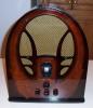
Hello, I always work on radios using isolation transformer. Once I am through I might play the radio for a while in my shop using the wall plug. Once when I did so I saw small spark when I connected the antenna ground. That ground is to a ground rod outside the house. Why would this be and is it a concern? The radio was a Philco 60.
Thank you, Dan
Posts: 1,135
Threads: 54
Joined: Feb 2013
City: Shenandoah,
State, Province, Country: Pennsylvania
Dan, it looks like there is a .015mfd going from one leg of the AC line to chassis ground. Be sure that has been replaced with a safety cap. If it has, that .015 is to remove some interference from the incoming line but also it can allow enough current to cause a slight spark when trying to attach an external ground wire but not enough to give you a shock when touching the chassis!
Ron
Bendix 0626. RCA T64 Philco 20B
Philco 41-250. Philco49-500
GE 201. Philco 39-25
Motorola 61X13. Philco 46-420 Crosley 52TQ
Philco 37-116. Philco 70
AK 35 Philco 46-350
Philco 620B. Zenith Transoceanic B-600
Philco 60B. Majestic 50
Philco 52-944. AK 84
Posts: 553
Threads: 89
Joined: Jun 2022
City: Marion
State, Province, Country: NY
Thanks Ron. Yes I always use a safety cap(s).
Dan
Posts: 5,653
Threads: 56
Joined: Sep 2008
City: Sandwick, BC, CA
I don't think it is really a concern, there may have been a small spark because whilst the neutral side of the household wiring is at zero, with respect to the two hot lines, it still may be above where an outside ground is, or even vice versa, so there may be a potential there rather then an electrical fault. This is also why I wince at people adding a grounded cable to an old radio with a grounded plug, the ground line runs all through the house and could be picking up electrical hash from anywhere. I've tried connected the ground terminal on an old radio to the power line ground but the results are mixed, sometimes it helps, often it does nothing but make the gain drop. On some sets you have to add am external ground because the volume control is in the antenna circuit and it won't work properly without it.
Regards
Arran
Posts: 2,327
Threads: 23
Joined: Jul 2020
City: Greenlawn
State, Province, Country: NY
On the Philco 60 schematic, there is that 0.015uF cap from chassis ground to the unswitched leg of the power line. One way of ensuring no "tickle" from the chassis is to install a polarized plug to ensure that the switch is on the hot side and the cap is on the neutral side.
A lot of sets have 2 caps. One each from each leg of the power inlet to chassis ground. This essentially puts the chassis at approximately 60V. I had one blow a fuse when the chassis touched the grounded frame of the display case that the chassis was on top of. (Edited 09/21/26 to make sense.) This is because one of the caps was shorted, a common problem with old paper caps across the AC Line. I suppose that on these sets grounding the chassis is important to allow for "common mode rejection" of incoming power line noise as well as completing the antenna circuit. Not grounding the chassis allows for the completion of the antenna circuit through the 2 caps to the power line, likely inducing noise.
"Do Justly, love Mercy and walk humbly with your God"- Micah 6:8
"Let us begin to do good"- St. Francis
Best Regards,
MrFixr55
Posts: 553
Threads: 89
Joined: Jun 2022
City: Marion
State, Province, Country: NY
Not sure anymore how I wired it. I sometimes use two safety caps on single cap sets. One on each leg. Not mine but the radio  . Seems like all my 30's Philco sets like my antenna ground. It quiets them right up.
Posts: 5,653
Threads: 56
Joined: Sep 2008
City: Sandwick, BC, CA
i think it's worth observing that Philco sets, unlike RCA or G.E, did not have an electrostatic shield on the power transformer, it's a band of copper foil wrapped around the outside of the core, and grounded to chassis, so Philcos, not having this, needed to have caps on the power line. Philco seemed to really like adding capacitors anyhow, they always seemed to use more paper caps in their circuits then other makes, at least in the 1930s and 40s, especially their early TV sets.
Regards
Arran
Users browsing this thread:
|
|
Recent Posts
|
|
under chassis parts locator diagram for 1938 Zenith 9s262
|
| Has anyone gone to the trouble of creating an under chassis parts locator image? Yes, I can identify components by foll...bobloney — 08:57 PM |
|
Plug Voltages Needed For A 1943 CRV-20130 Power Supply
|
| Try looking at this site the book mark is for a old generator that I was given. David https://radionerds.com/index.ph...David — 08:36 PM |
|
Plug Voltages Needed For A 1943 CRV-20130 Power Supply
|
| Hello Everyone,
I am looking for voltage identification for all the pin positions on the socket of a CRV-20130 power su...Tonym4704 — 08:16 PM |
|
Philco P45-6365 Universal Transformer Instruction Manual
|
| Can anyone guide me to where this may be found?GRG — 03:00 PM |
|
54C Complete Teardown/Rebuild
|
| I don't think that I have encountered a 12Z3 before, curious how it uses one of those but includes a #43, which is a 25 ...Arran — 02:17 PM |
|
HiFi (Chifi) tube amp build - but my own design.
|
| It's the other forum. I'm also in DIY, but mostly read there. Honestly, I kinda jumped into this without much thought to...TV MAN — 10:43 AM |
|
Philco 71 Code 125
|
| Hello,
I am in need of a schematic for this radio. Mine has the three separate circular tube shields and a shadow me...dconant — 08:06 AM |
|
Stromberg Carlson 1500 Squeal
|
| And life just keeps getting more complicated.dconant — 07:57 AM |
|
54C Complete Teardown/Rebuild
|
| Hello Roy,
here is this one
sincerely Richardradiorich — 12:45 AM |
|
54C Complete Teardown/Rebuild
|
| Richard,
Had grabbed it already but thank you just the same. I find myself wanting to find some way to block out the...glyphmon — 12:03 AM |
|
Who's Online
|
There are currently 1953 online users. [Complete List]
» 1 Member(s) | 1952 Guest(s)
|
|
|

|
 
|