07-06-2013, 09:56 PM
Just wanted to show this one.
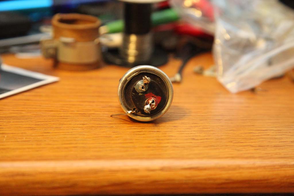
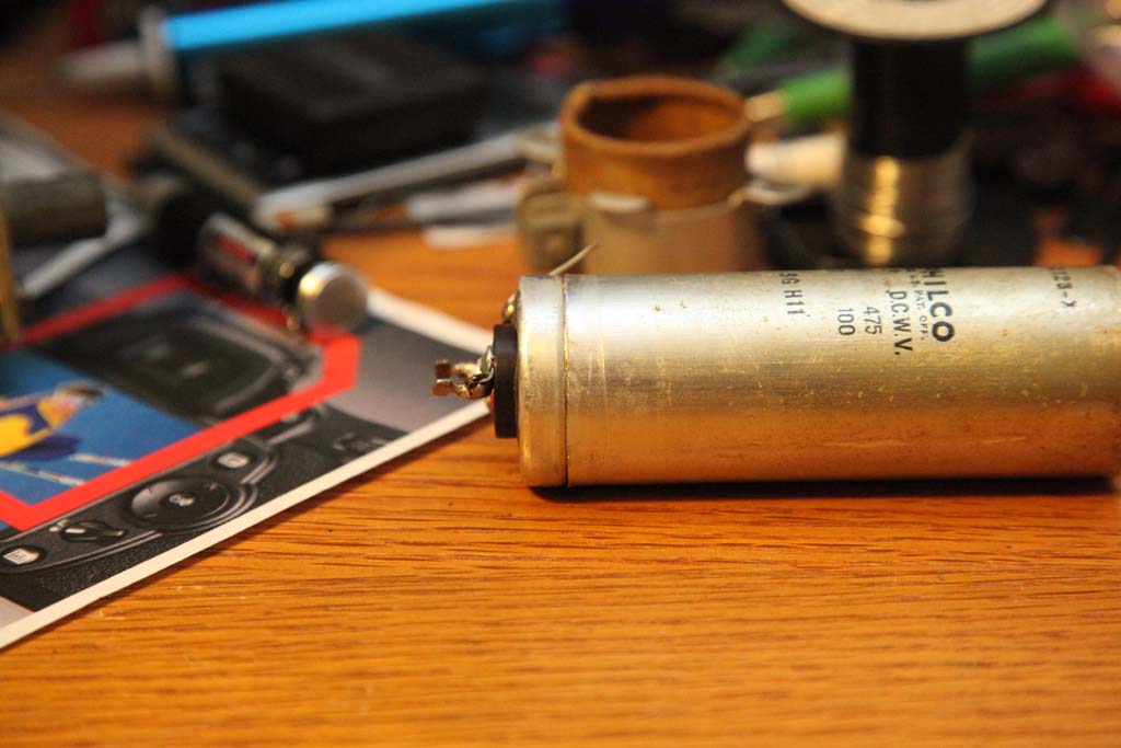
This is the dual 8uF 475V + 10uF 100V cap.
This is the cap that is filtering the rectifier right after the choke plus filtering the Chassis to the rectifier minus. Common goes to the rect. minus, and two pluses respectively to the choke output and to the Chassis.
Now since this is the output after the choke large ripple current rating is no longer required but since I do have nice 22uF 350V caps rated at 350mA, I decided to use two in series, so this way I get an 11uF cap at 700V and 350mA ripple. Which is plenty. For decoupling the Chassis I used what was used before - 10uF 100V cap, general purpose ad there is no large ripple current here plus the Chassis is also filtered by an additional choke.
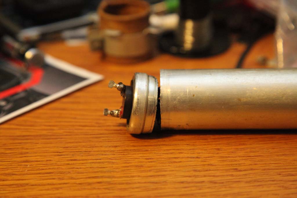
Anyway, there are two different cap types in the DC filter and while one is the "cap type", this one is the "low waste type", that is right at the bottom there is an indented band.
I used a pipe cutter to cut the bottom at the highest part of that "waste".
Then I cleaned it, drilled the cap's terminals, drilled a hole in the insulator for the negative common, connected the three capacitors together and threaded their wires through the respective holes. I kept the color code - the high voltage cap goes to Red terminal and the 100V one - to Green.
The photograph does not show it - I potted the caps' bases (only bases, not to cover the caps) with some hot glue for stabilizing them from shaking, vibration etc.


![[-] [-]](https://philcoradio.com/phorum/images/bootbb/collapse.png)


