Posts: 200
Threads: 36
Joined: Jul 2016
City: Spring Lake MI
Hi guy's, working on a "70" of which the RF-Coil primary is open, what should the reading be across the primary winding. I need to rewind it, have not done this before. I have the info from the Philco Bench on RF-Coils no info for the inductance.
Thanks
Jim
Spring Lake MI
Posts: 16,476
Threads: 573
Joined: Oct 2011
City: Jackson
State, Province, Country: NJ
Jim
Unless there is data available, the best way is to unwind the coil counting the turns and then see what gauge it is (calipers will do) and wind it using the same or larger gauge (larger is fine as long as it fits in the bobbin).
The reading is not important; what important is the number of turns and, in case of tuned circuit, the length of the winding in total (affects inductance; this is why for this type of coils the gauge should be observed).
Ohms are not really a parameter with coils, it is a parasitic.
People who do not drink, do not smoke, do not eat red meat will one day feel really stupid lying there and dying from nothing.
Posts: 44
Threads: 4
Joined: Dec 2013
City: Freeport, LI, NY
Hi Jim.....
I just finished rewinding 2 coils out of a Model 84.....the Ant. and Osc. coils. Both the primaries had the "Green Gunge". This is a chemical reaction between the silk covered #36 primary coil and the celluloid underlay. Moisture, I'd assume, would be a factor in this.
Use #36 enamel wire as a replacement. Don't worry about the turns needed.....measure the width of the old coil with a micrometer, remove the old wire, lay in the new to the same width dimension. Remember, the new wire has to be laid in the same direction as the old! And, be careful around the celluloid....it pretty fragile if you want to keep it. Doing the whole job under an illuminated magnifying lamp would make the going a lot easier. (wish I had one!)
Good luck with the project and all of us here are expecting a full report when you're finished.
A Merry Christmas and a Happy Near Year!
...Jim
Posts: 16,476
Threads: 573
Joined: Oct 2011
City: Jackson
State, Province, Country: NJ
For 1st and 2nd RF yes, the primary number of turns is not that important (though I would try to stick reasonably close to original).
For the IF coil (#19) both windings have to be as close as possible to the original as they are part of tuned circuit.
People who do not drink, do not smoke, do not eat red meat will one day feel really stupid lying there and dying from nothing.
Posts: 200
Threads: 36
Joined: Jul 2016
City: Spring Lake MI
Thank you for your posts.........................
Jim
Spring Lake MI
Posts: 1,204
Threads: 84
Joined: Jan 2014
City: Annapolis, IL
State, Province, Country: USA
Jim, here is my thread on restoring one of these. Mike (Morzh) has at least one thread on his also. http://philcoradio.com/phorum/showthread.php?tid=8626 Here you can see what I ran into, how I fixed, and some of my mistakes. I too had to redo the RF coil. Some of the links may not work since some things have been moved within the website. Have fun 
Tech section and notebook has some info on this radio too.
If I could find the place called "Somewhere", I could find "Anything" 
Tim
Jesus cried out and said, "Whoever believes in me , believes not in me but in him who sent me" John 12:44
(This post was last modified: 12-23-2016, 04:26 PM by TV MAN.)
Posts: 200
Threads: 36
Joined: Jul 2016
City: Spring Lake MI
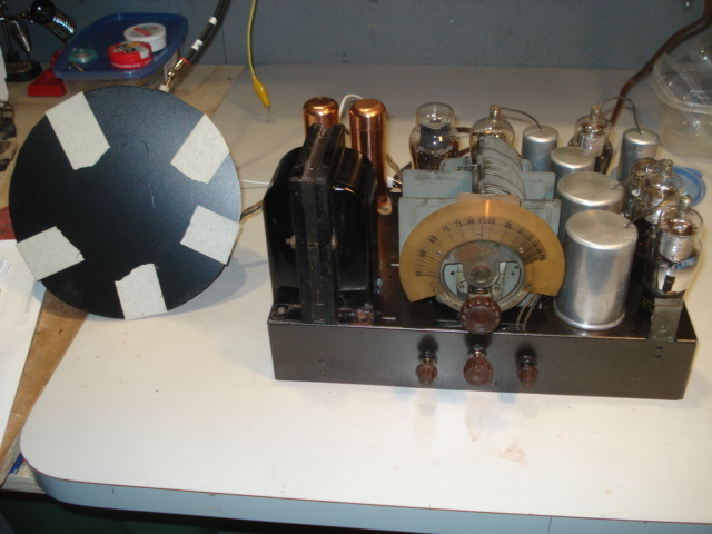
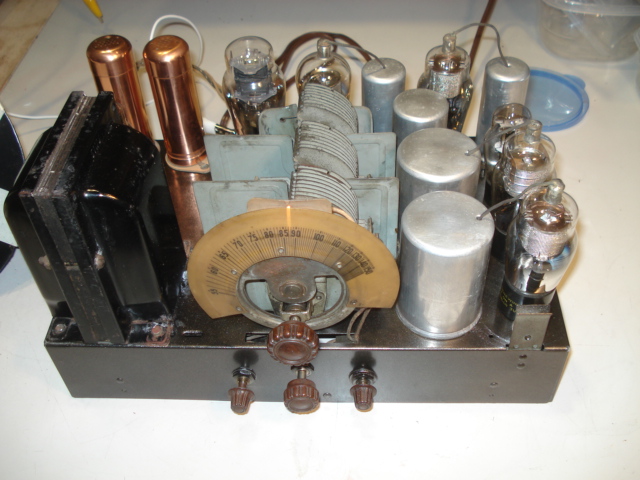
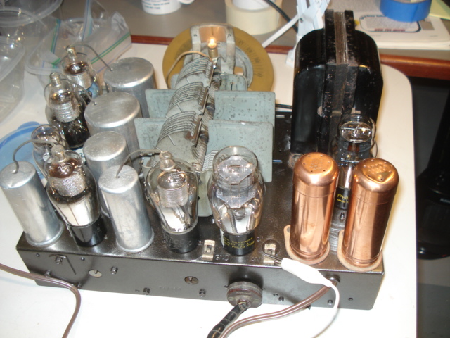
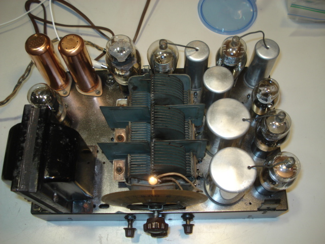
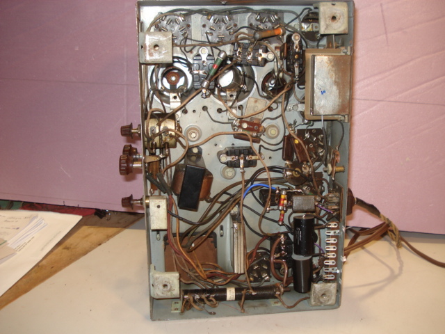
Hi guy's and Merry Christmas......had a good Christmas, got the Philco 70 up and running after a recap and rewound the RF Coil did some cleaning and painting on the chassis.
The alignment schematic shows three adjustments on the back of chassis but this one has only two. According to the tube configuration this is the early model below B22,000? I can find only one alignment procedure, is there another one. I do have document's from the Chuck at the Philco Repair Bench.
Also the volume seems a little down on distance station's the strong local stations are fine.
I want to thank all you guy's on this forum and the one's that responded to my post's
Here are some pic's. Do have some work on the cabinet, but I'm over the hump as they say.
Jim
Spring Lake MI
Posts: 1,409
Threads: 72
Joined: Oct 2007
City: Linn Creek, MO
Could it be that you missed the one that has a metal cover over it? It is all the way to the left side of the chassis. This one is covered because, the trimmer has B+ voltage on it.
Steve
M R Radios C M Tubes
Posts: 200
Threads: 36
Joined: Jul 2016
City: Spring Lake MI
(12-25-2016, 02:12 PM)Steve Davis Wrote: Could it be that you missed the one that has a metal cover over it? It is all the way to the left side of the chassis. This one is covered because, the trimmer has B+ voltage on it.
Steve Wow am I losing it thank you so much...........
Jim
Spring Lake MI
Users browsing this thread:
|
|
Recent Posts
|
|
Need to purchase some accessories for restoration of my Old Philco Radio
|
| Hi Paulo,
Welcome to the Philco Phorum.
I can see why you want to find good reproduction parts. That is a bea...MrFixr55 — 11:10 PM |
|
HiFi (Chifi) tube amp build - but my own design.
|
| Tim,
I have some bakelite sockets in my work shop that I can dig up. I believe quite a few are NOS. I will take photo...RodB — 10:03 PM |
|
Philco 610B oscillator wiring
|
| > The cathode as noted is wired directly to the ground side of the heater filament for that tube, not to the #17 and ...Radioroslyn — 08:12 PM |
|
HiFi (Chifi) tube amp build - but my own design.
|
| Tim;
I noticed your post a little late, but I would take one of the junk sockets and try to break a chunk out of it wi...Arran — 08:07 PM |
|
Need to purchase some accessories for restoration of my Old Philco Radio
|
| Here is a list of resources found in our online library that you might find useful. Mike's Gobs of Knobs email addres...klondike98 — 01:46 PM |
|
First Radio restoration
|
| Hi Tubeman,
Welcome to the Philco Phorum. Phamily Phriendly Pfun with Phine Pholks Phull of Philco Phacts. (See a p...MrFixr55 — 12:33 PM |
|
First Radio restoration
|
| You could post in the WANTED ADs section here on the Phorum and see if anyone has an RF generator that they want to sell...klondike98 — 11:55 AM |
|
Zenith H725
|
| Good ideas, thank you Arrange and Rich. I have the adhesive aluminum foil already and can try that immediately.
More ...EdHolland — 10:18 AM |
|
Graphics for majestic 1050 dial glass.
|
| Murf;
I found this thread on the ARF, the first photo has a pretty good view of the dial glass.
Regards
ArranArran — 01:12 AM |
|
Zenith H725
|
| hello Ed,
how about that speacial tape used for ducting it's like foil or how about thin piece of
aluminum roof flash...radiorich — 12:19 AM |
|
Who's Online
|
| There are currently no members online. |

|
 
|


![[-] [-]](https://philcoradio.com/phorum/images/bootbb/collapse.png)


