Welcome Guest! Be sure you know and follow the Phorum Rules before posting. Thank you and Enjoy! (January 12) x

Thread Closed
Thread Rating:
  • 1 Vote(s) - 5 Average
  • 1
  • 2
  • 3
  • 4
  • 5

Peerless Radio Find
#16

If you compare the photos of the Clinton and the Silver, the knobs are the same (except the Silver looks like it has a different one at the far right). My guess is yours had the same round knobs and someone swapped them at some point.

By the way, here's yet another re-badge of your radio, this one sold as a Phillips

https://s-media-cache-ak0.pinimg.com/236...f760a5.jpg

Greg

"We are here to laugh at the odds and live our lives so well that Death will tremble to take us."
#17

I decided it's time to post something new. 

Here's a follow up on the mods to the not so desirable circuit design of this Peerless/Clinton 139. First is the original detector design.        So because there is no AVC the volume goes all over the place. I am thinking can I add AVC to this circuit without too much grief. 
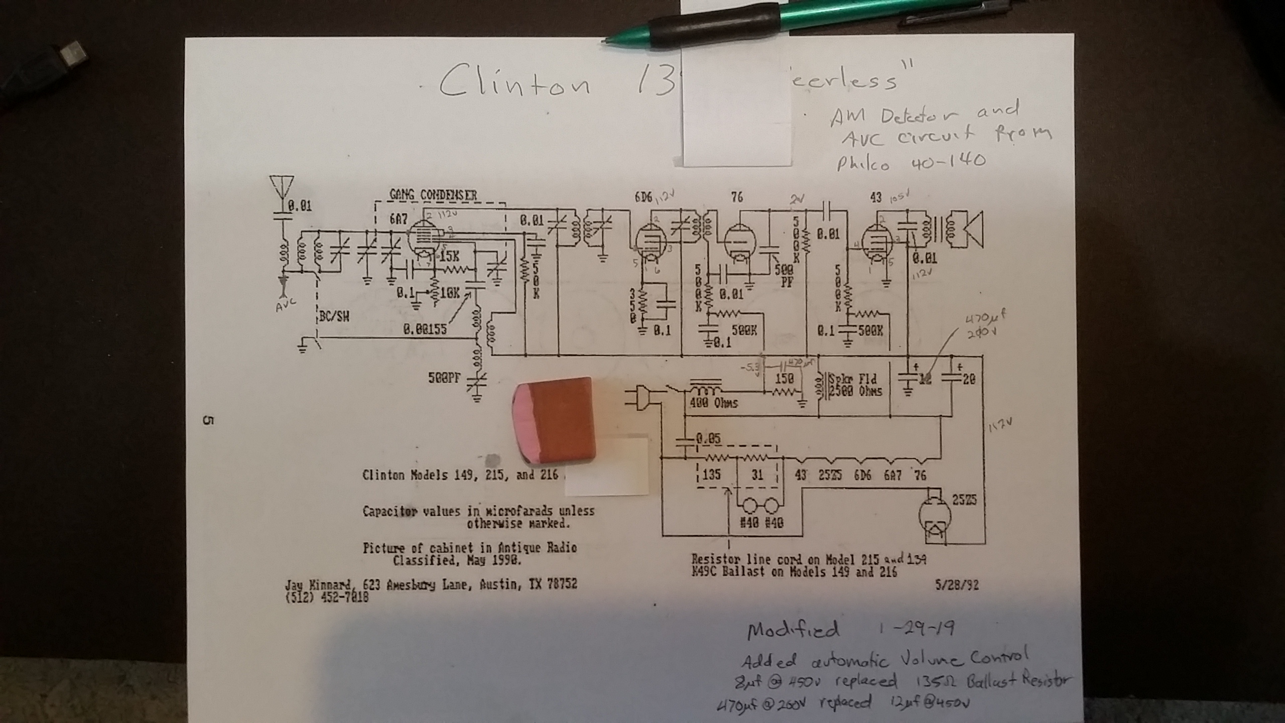
Now here' are the mods. The the detector, the ballast resistor, and the filter cap. 

The detector circuit is from a Philco 40-140 with AVC. I cheated and used germanium diodes and reused the 76 tube as a just audio preamp. So the AVC works fair. I attached to where the ground was for the first antenna coil is.  It only varies the first RF stage gain. I also added a filter cap to the bias voltage for the 76 tube.

I know I used too big a filter cap at the rectifier. So I am thinking I will add series resistor with the large cap. This should lower the peak rectifier current and still keep the ripple hum down.

And last is the ballast resistor. I replaced it with an 8uf motor run cap. It took a few tries to find just the right value. I measured the filiment voltage of the 25Z5 tube for this. It takes a little longer to warm up but it works with no resistor heat. 

I made these mods some time ago. And still need to add the series resistor to the rectifier cap. I will try and post the results.


Attached Files Image(s)
   

!!!!!!!!!!!!!!!!!!!RESISTANCE IS FUTILE!!!!!!!!!!!!!!!!!!!!!!  
                           /\/\/\/\/\/\/\/\/\
                                                     
                                 [Image: http://philcoradio.com/phorum/images/smi...on_eek.gif]  Chris
#18

I doubt that resistor was original. I think it was someone's mod to replace the CB cord.
8 uF sounds about right. This is what I used in AA5s with CB cords.

People who do not drink, do not smoke, do not eat red meat will one day feel really stupid lying there and dying from nothing.
#19

You could if wanted SS the 25Z5 by using an old base and adding 3 diodes. One across the heater pins and the other two the plate to cathode. No heat and more B+++++++. I've used it in a few sets but not w/a cap dropper

GL w/your project!

When my pals were reading comic books
I was down in the basement in my dad's
workshop. Perusing his Sam's Photofoacts
Vol 1-50 admiring the old set and trying to
figure out what all those squiggly meant.
Circa 1966
Now I think I've got!

Terry
#20

Today I changed the first filter cap from 450uf to 33uf this should lower the peak rectifier current.  Then redrew the power supply so it made sense.

 I also drew in the ground at the 6A7 cathode where it use to have the volume control attached to it. 

I also decided that it had too much audio gain after changing the 76 tube from detector to audio amp.  and added some resistors to the volume control. I know I could have added a resistor the the 76 cathode and may try this instead. 

 After looking closer at the power supply I moved the power switch to hot side of the cord with a 2 amp fuse and made sure the neutral side went to the chassis part of the bias circuit. (it's a polarized plug) Now I only have 10vac from the chassis to earth ground.    

!!!!!!!!!!!!!!!!!!!RESISTANCE IS FUTILE!!!!!!!!!!!!!!!!!!!!!!  
                           /\/\/\/\/\/\/\/\/\
                                                     
                                 [Image: http://philcoradio.com/phorum/images/smi...on_eek.gif]  Chris
#21

this thread will come in very handy, as we have one too!  But it's a 'GENERAL'


Users browsing this thread:
[-]
Recent Posts
Need to purchase some accessories for restoration of my Old Philco Radio
Here is a list of resources found in our online library that you might find useful. Mike's Gobs of Knobs email addres...klondike98 — 01:46 PM
First Radio restoration
Hi Tubeman, Welcome to the Philco Phorum.  Phamily Phriendly Pfun with Phine Pholks Phull of Philco Phacts. (See a p...MrFixr55 — 12:33 PM
First Radio restoration
You could post in the WANTED ADs section here on the Phorum and see if anyone has an RF generator that they want to sell...klondike98 — 11:55 AM
Zenith H725
Good ideas, thank you Arrange and Rich. I have the adhesive aluminum foil already and can try that immediately. More ...EdHolland — 10:18 AM
Graphics for majestic 1050 dial glass.
Murf; I found this thread on the ARF, the first photo has a pretty good view of the dial glass. Regards ArranArran — 01:12 AM
Zenith H725
hello Ed, how about that speacial tape used for ducting it's like foil or how about thin piece of aluminum roof flash...radiorich — 12:19 AM
Zenith H725
Ed; One material that I have seen, but never tried for this was material for making exhaust gaskets, it's similar to ...Arran — 11:42 PM
Zenith H725
I just remembered, I have some hi temp silicone rubber material which could do the trick. Or a piece of FR4 laminate. Th...EdHolland — 08:39 PM
Zenith H725
The PSU filter cap arrived today (thank you USPS!) so I will work on that later. Meanwhile, I have the dial, speaker...EdHolland — 06:42 PM
Philco 610B oscillator wiring
Thanks Terry. After checking my notes I think I recorded about -10v at the 6A7 G4/control grid. The screen grid (G3 &...Tubester — 05:59 PM

[-]
Who's Online
There are currently no members online.

>