RCA/Victor R-35 / R-39 / RE-57 Speaker Lead Terminals
Posts: 185
Threads: 8
Joined: Apr 2023
City: Roanoke
State, Province, Country: Virginia
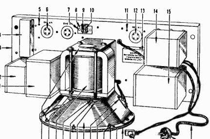
Does anyone have a Victor R-35 / R-39 / RE-57 that you can easily look at or which you have restored? I am creating new speaker cables for my Universal Shop Speaker and Dummy Field Coil. My R-39, which is awaiting restoration, is in storage and not easy to access. I have looked at the illo of the R-35 / R-39 / RE-57 terminal board in the 1929-1930 Red Book. Are those speaker cable leads attached with spade lugs or some other terminal held by machine screws? If so, what type of terminal and what size machine screw?
Dale H. Cook, GR/HP/Tek Collector, Roanoke/Lynchburg, VA
https://plymouthcolony.net/starcity/radios/
Posts: 1,291
Threads: 11
Joined: Jul 2020
City: Greenlawn
State, Province, Country: NY
Hi Dale,
No, I have not repaired one of these but since the speaker on this unit is attached to the amplifier chassis, I would suspect that the leads are soldered to the terminals, and those terminals are likely only for the voice coil. The earlier models R32, R52, etc. used what looks like a 4 pin Jones connector., as these speakers were not connected to the amp chassis. My GE S-22A (RCA R7A) has a rather similar speaker.
I think that these radios were designed and built just before the acquisition of Victor by RCA. The amplifier is rather similar in layout and circuit to the Radiola 80, which (I believe) is the first RCA radio built in the Camden, NJ Victor plant instead of being built by GE or Westinghouse.
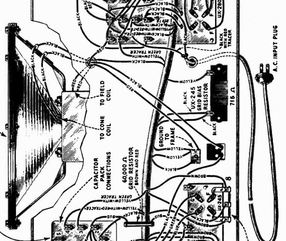
Attached below are pictorials of the Victor R-35 and the Radiola 80, bearing out the likelihood that the speaker connection is soldered at 2 terminals on a strip for the voice coil and the field coil leads being pigtails directly from the coil.

 From what I can discern, the only difference between the Radiola 80 and the Victor R35Amp Chassis are the method of connecting the radio chassis and the fact that the Field coil is in the B return side on the Radiola 80 as opposed to being on the B+ side on the Victor.
In my book, this is a cool radio, as it was Victor's entry into building their own radios (they previously bought Radiola 16s, 17s or 18s from RCA.
"Do Justly, love Mercy and walk humbly with your God"- Micah 6:8
"Let us begin to do good"- St. Francis
Best Regards,
MrFixr55
Posts: 21
Threads: 2
Joined: Dec 2021
City: Grafton
State, Province, Country: ON
Posts: 185
Threads: 8
Joined: Apr 2023
City: Roanoke
State, Province, Country: Virginia
JimSirt Wrote:Next photo is the other end of the speaker cable and has a 4 pin plug with a round pin position locator and the third photo of the receptacle mounted on the PS/Amp chassis.
That is a pre-WWII plug and socket made by Howard B. Jones, which was later part of Cinch-Jones. I know it is pre-WWII because of the round cap on the plug. By 1942 Jones was using only rectangular caps (at least, that is all I have seen in catalogs). They were still making the same 4-pin plugs and sockets with the polarizing pin in 1942. Also, MrFixr55 discussed the use of the Jones plugs on earlier Victor models.
I have good illos of the R-35 / R-39 / RE-57 speaker chassis in the 1929-1930 Red Book (all three models used the same chassis), along with a full parts list. The R-39 chassis did not use a Jones plug (which is shown in the 1929-1930 Red Book for the RE-45).
As far as I can tell the speaker chassis in the R-35 / R-39 / RE-57 is unique. I am leaning toward the suggestion of MrFixr55 that the cable was soldered to lugs. I will probably have to wait until I have the chance to get at my R-39 in storage to find out.
Dale H. Cook, GR/HP/Tek Collector, Roanoke/Lynchburg, VA
https://plymouthcolony.net/starcity/radios/
Posts: 1,291
Threads: 11
Joined: Jul 2020
City: Greenlawn
State, Province, Country: NY
Hi Jim,
Your RE45 radio with Electrola (electric Victrola with magnetic pickup) was based on the earlier R-32, which (I believe) is the first radio that Victor manufactured. Your speaker has a plug, likely because the speaker is cabinet mounted, and appears to be the GE Kellog-Rice speaker that all electrodynamic (and PM Dynamic) speakers are based on. The R 35, 39, Radiola 80 and R7 Suprette speakers are similar but with a different frame. The wires on the 80 and R7 Suprette are confirmed by pics to be soldered. If the Radiola 80 are soldered, it is likely that the R35, R39 and RE57 (similar amp chassis to the Radiola 80) are also soldered. Flr the R35, 39 and Radiola 80, the pigtail from the radio chassis connects to the amp / PS Chassis via screw connectors, as opposed to the Jones connector that yours uses.. BTW, I think that the RE45 is a cool radio. How does the Phono sound? The cartridge is no GE RPX let alone a Pickering, Shure, Otofon, etc., but it IS magnetic! (If I bought one of these, Ms. Fixr would fix my wagon but good!
"Do Justly, love Mercy and walk humbly with your God"- Micah 6:8
"Let us begin to do good"- St. Francis
Best Regards,
MrFixr55
Posts: 21
Threads: 2
Joined: Dec 2021
City: Grafton
State, Province, Country: ON
Thank you Dale and MrFixr55 for the great info. I bought the RE-45 last year but I haven't had a chance to check it over, so no idea yet about the phono. The entire unit is in amazing condition, never been barn or garage stored. Weigh's a ton. I'll probably get to the restoration this winter.
Jim
Users browsing this thread:
|
|
Recent Posts
|
|
Philco Model 38-7: what caps & resistors do fail typically?
|
| Since you stated earlier, you have a console 38-7XX. They also had a 38-7T (table), and 38-7CS (chairside). A very nic...GarySP — 01:18 PM |
|
Part numbers to model cross
|
| That I wouldn't know, but sometimes the radio document itself shows one, same as the capacitor cans' etc pinouts.morzh — 12:46 PM |
|
Part numbers to model cross
|
| Thank you morzh, that is exactly what I was looking for. Now , is there some where that shows pinouts for Philco power ...Jim Dutridge — 11:37 AM |
|
Restoration of the Canadian General Electric A-87
|
| Thanks for your help Michael. In fact, this video is only an intermediate result. Later I had to apply another tinting l...RadioSvit — 09:01 AM |
|
Restoration of the Canadian General Electric A-87
|
| Great job on the cabinet.
PS. In the US notation, "kenotron" refers to specific type of tubes; we call re...morzh — 08:24 AM |
|
Part numbers to model cross
|
|
This document has at least some tables of models and parts used.
Example: Choke 32-7572, used in 604 radio.
Search f...morzh — 08:19 AM |
|
Restoration of the Canadian General Electric A-87
|
| I also checked all the radio tubes on my Hickok 530 tube tester. The 5Z3 kenotron turned out to be faulty, all the other...RadioSvit — 08:02 AM |
|
Restoration of the Canadian General Electric A-87
|
|
Well... While the varnish is drying up, I started repairing the chassis...
Of course I started by replacing the pa...RadioSvit — 07:12 AM |
|
Philco Model 38-7: what caps & resistors do fail typically?
|
| Hello Martin,
Welcome aboard our little community what great Model 38-7
Sincerely Richardradiorich — 12:30 AM |
|
Philco Model 38-7: what caps & resistors do fail typically?
|
| Welcome to the Phorum Martin.
I count about 9 paper caps, the 3 electrolytic caps and 2-Y2 safety caps to replace th...RodB — 09:44 PM |
|
Who's Online
|
| There are currently no members online. |

|
 
|


![[-] [-]](https://philcoradio.com/phorum/images/bootbb/collapse.png)


