Philco newbie with P-1891-WA console questions
Posts: 3
Threads: 1
Joined: May 2025
City: Meadow Valley
State, Province, Country: California
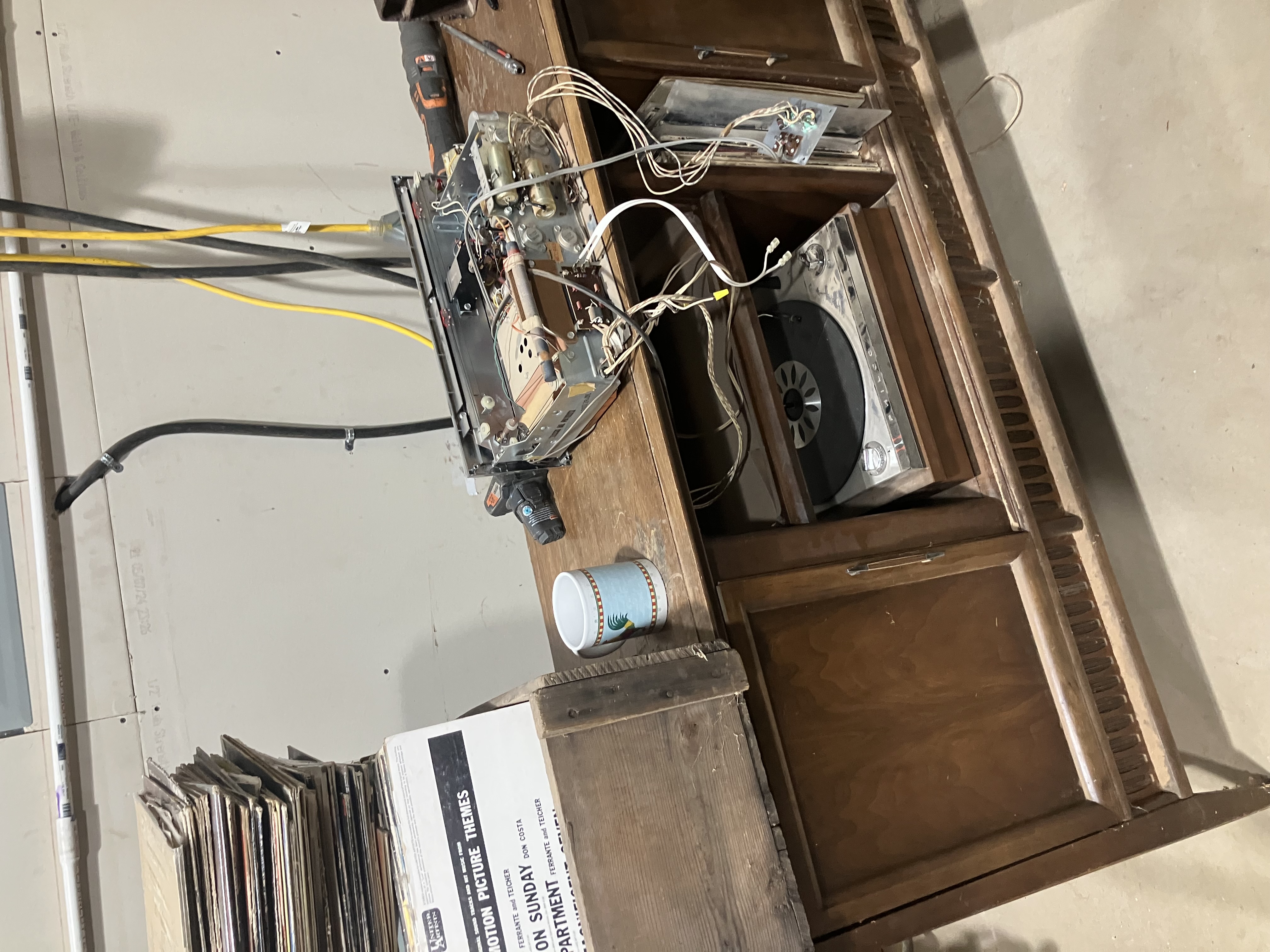
I’m very new to vintage solid state repair and have many questions but will stick to some broad descriptions of what’s going on with this unit and what I’ve done so far.
The thing “works” as in it puts out sound from both radio and record player but the sound is … muffled, crackly, and all around weak. I’ve contact cleaned the potentiometers and got less “crackle” so happy with that.
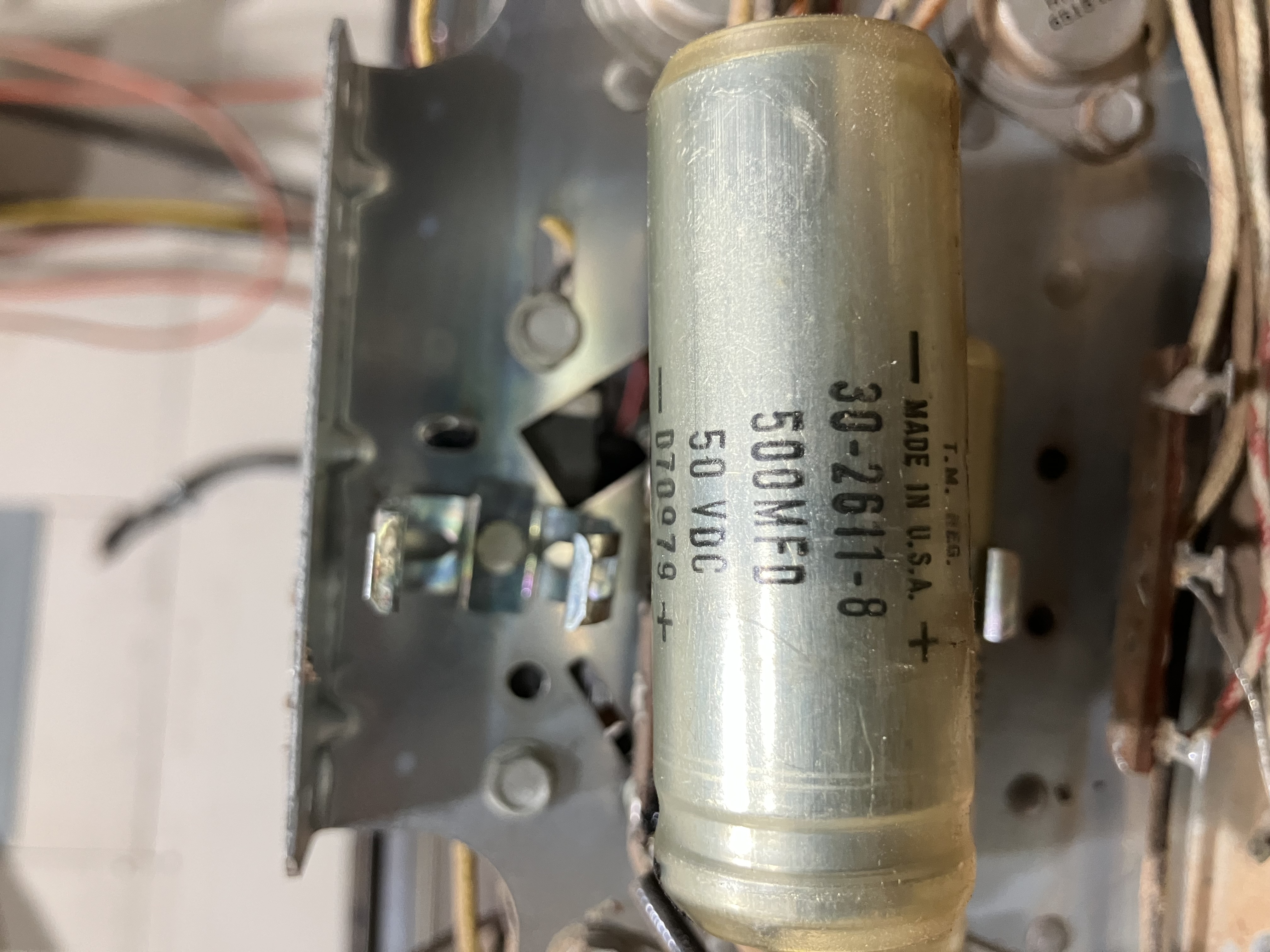
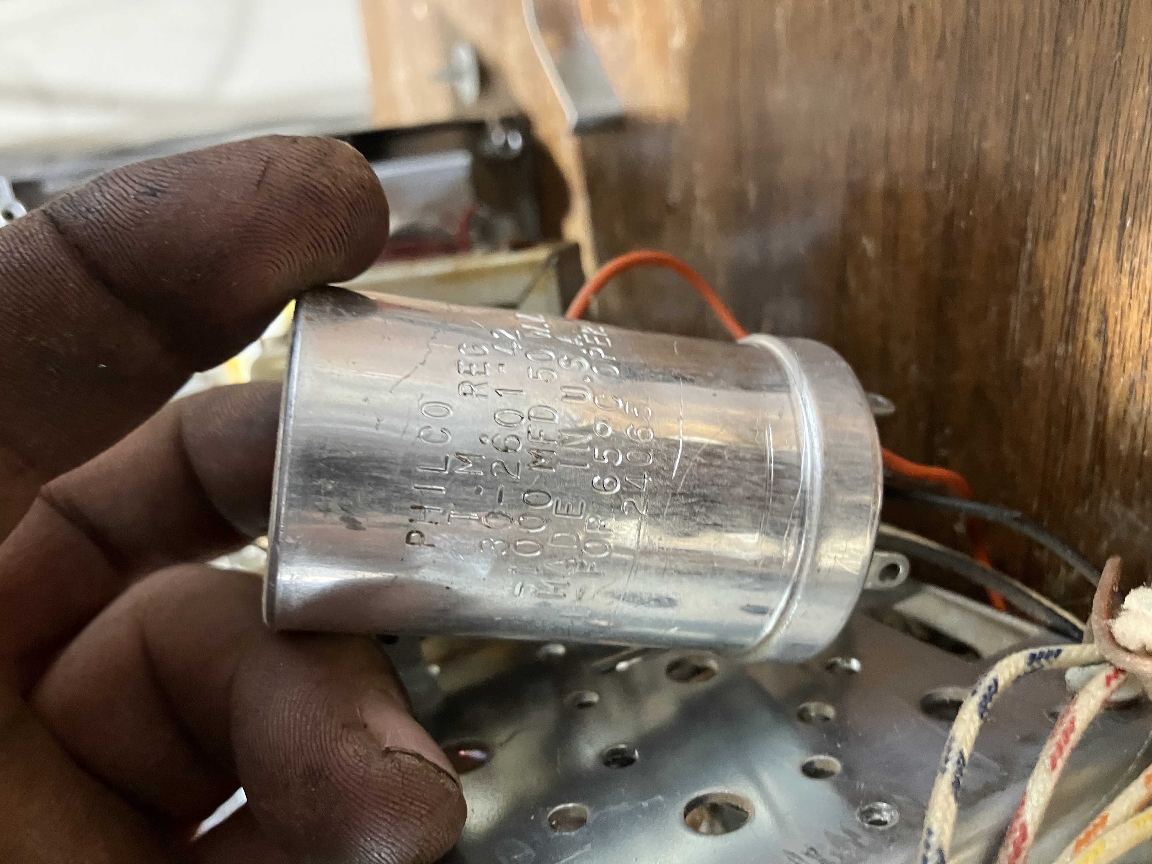
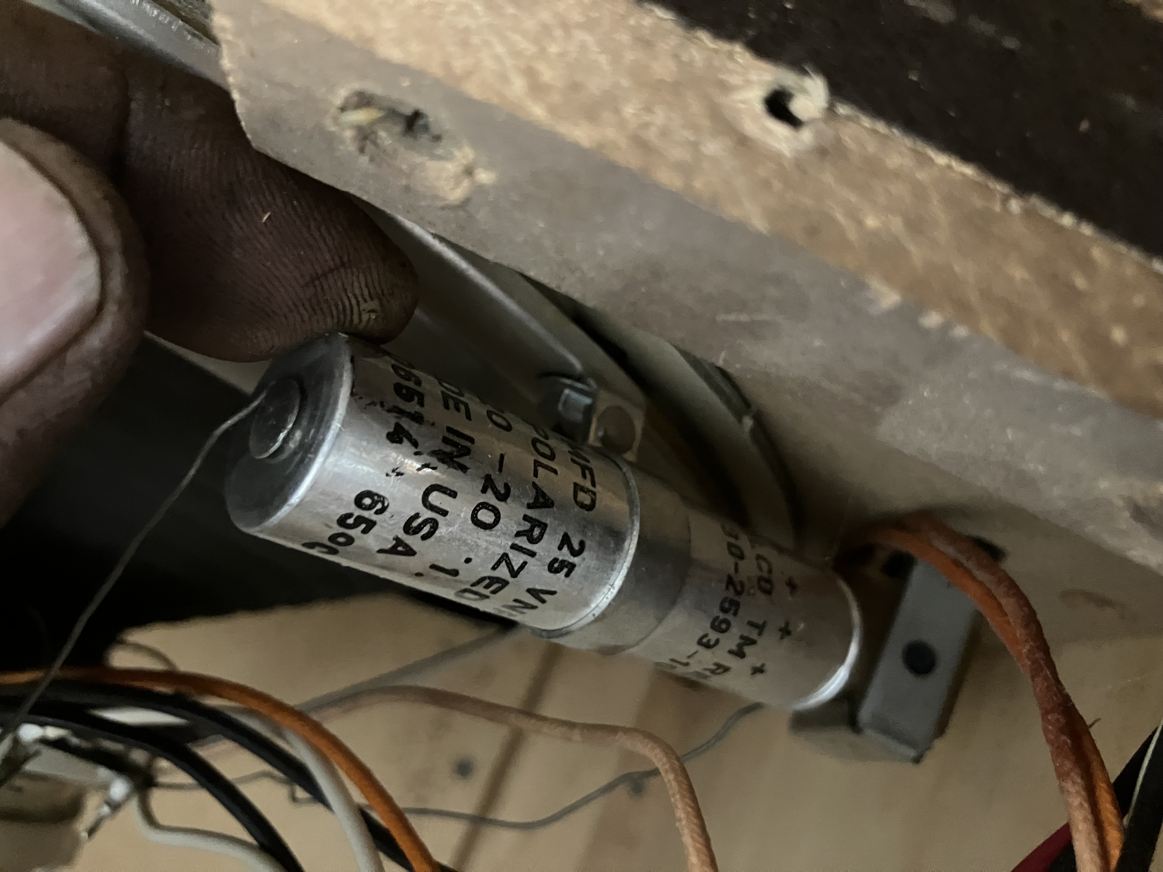
My internet research has taught me terms like recapping, output transistors, speaker coils, speaker capacitors, transformers, etc. I am gleaning consistent info suggesting replacing power in and speaker capacitors, checking output transistors, and cleaning speaker coils.
Sound like a good place to start?
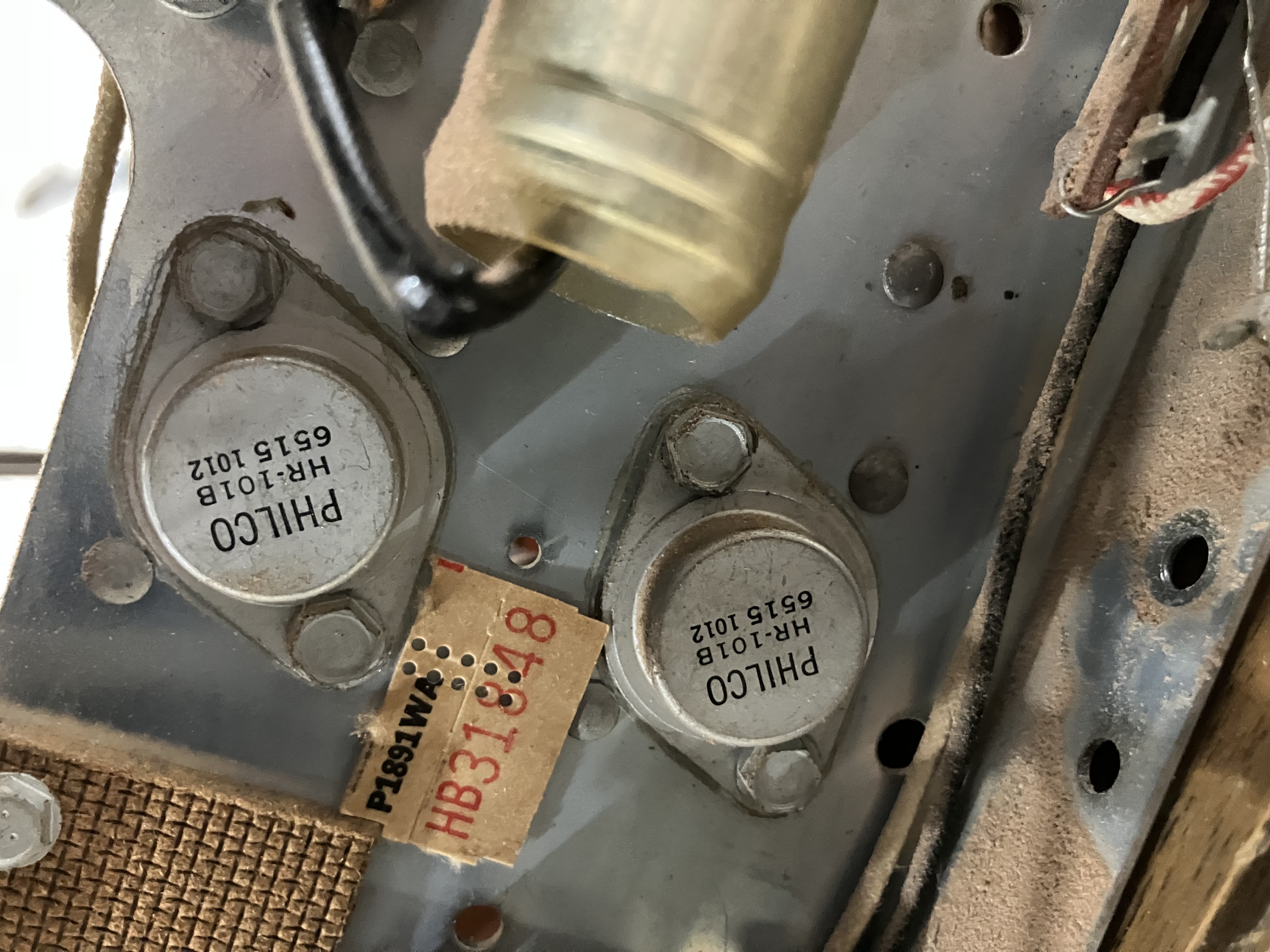
If so, how do I know if my output transistors are “NPN” or”PNP”? They are labeled philco HR101B 6515 1012. And what is a good way to insulate the base of them back to the heat sink? Also, they just pull out, the leads are not soldered to anything. Problem? Or normal?
Also don’t know how to check speaker coils besides if they are shorted. Can’t find info on if they’re wearing out (do they?) Anyway, that seems to be a good start. I’ll try to get my 10 yr old daughter to show me how to post photos if deemed necessary!
Thanks
Posts: 2,172
Threads: 158
Joined: Jan 2013
City: Westland, MI
Welcome to the Phorum, Jeffcon! Replacement of the caps is a priority. Several threads are here with information on restuffing capacitor cans. Many of our members dabble in the early solid-state, so it shouldn't be long before others chime in! Take care, - Gary
"Don't pity the dead, pity the living, above all, those living without love."
Professor Albus Dumbledore
Gary - Westland Michigan
Posts: 3
Threads: 1
Joined: May 2025
City: Meadow Valley
State, Province, Country: California
Thank you! My little pea brain has been getting overwhelmed with TMI so I’m looking for some hand holding before I consider taking off the training wheels! Any insight anyone is willing to give would be much appreciated!
Posts: 5,177
Threads: 276
Joined: Nov 2012
City: Wilsonville
State, Province, Country: OR
We don't have information on a radio that "new" in the digital library but Sam's Photofacts has the schematic you can buy:
https://www.samswebsite.com/en/photofact.../id/115739
Posts: 1,144
Threads: 47
Joined: Feb 2015
City: Roseville, MN
Hello Jeffcon,
Welcome to the Phorum. You've taken a risky step in powering up 65-year-old electronics without having some form of protection. Luck was on your side, build yourself a "dim bulb" for this purpose. Since there's noise coming from the speaker you can probably eliminate, at least for now, the possibility the speaker voice coil I bad, though it could be rubbing on the magnet. Coils don't generally wear out, they either have a break in the wire or can short circuit to an adjoining wire. To test a coil of wire you will need a multimeter set to read ohms, then test the coil with the test leads and if you get a reading on the meter the coil is intact. This is the first thing I check when I work on a radio. If any coils are open circuit then it's a good bet the radio won't work and it's good to know this early on.
Since you have already "tested" most of the circuitry you can concentrate on what should be replaced, like capacitors. You can start with the power supply filter capacitors. Those aluminum cans are electrolytic capacitors and over time they deteriorate and become ineffective. Some of them have multiple capacitors within the can, these will have more than two connections. You can replace them with multiple single units. At this point I should mention you will have to know how to wield a soldering iron. Also it's really handy to be proficient in reading a schematic diagram so you can check off parts as you replace them and you will be able to get a replacement parts list. One more thing about the power transistors, they plug into connectors and since you have removed one you will have to coat the bottom with a silicon grease so the transistor can dissipate heat to the heat sink.
Keep asking questions so we know how you're coming along. It's a lot to learn, so be patient and careful.
Posts: 16,524
Threads: 573
Joined: Oct 2011
City: Jackson
State, Province, Country: NJ
Full recap is a no-brainer.
By full I mean full. No caps, with the sole exclusion being ceramics/mica, if present, should remain.
I won't be surprised if after that it will just work.
People who do not drink, do not smoke, do not eat red meat will one day feel really stupid lying there and dying from nothing.
Posts: 3
Threads: 1
Joined: May 2025
City: Meadow Valley
State, Province, Country: California
Thanks RodB and morzh, Am I using incorrect terminology regarding output transistor question whether they’re NPN or PNP? Seems to be different testing methods for each type.
Capacitors…. Cross reference for replacement capacitors, especially the large one is beginning to frustrate the heck out of me! Inernet search for comparable output transistors has yielded nothing useful to me. It could be so simple until it’s not.
Posts: 878
Threads: 51
Joined: Feb 2013
City: Shenandoah,
State, Province, Country: Pennsylvania
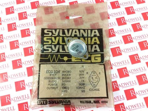
Hi Jeffcon, your HR-101 transistors cross reference over to an ECG-104 or RCA SK 3719 or an NTE104. It’s a PNP Ge (germanium) power output transistor!
Ron
Bendix 0626. RCA T64 Philco 20B
Philco 41-250. Philco49-500
GE 201. Philco 39-25
Motorola 61X13. Philco 46-42 Crosley 52TQ
Philco 37-116. Philco 70
AK 35 Philco 46-350
Philco 620B. Zenith Transoceanic B-600
Philco 60B. Majestic 50
Philco 52-944. AK 84
Posts: 16,524
Threads: 573
Joined: Oct 2011
City: Jackson
State, Province, Country: NJ
Start with recap.
Address transistors only if needed.
Testing transistors is simple and is best done with an analog ohmmeter.
If it is a PNP, then:
- Unsolder two wires that are not connected to the case (the pins). In case all three terminals are insulated pins, unsoder any two.
- Locate the terminals designations: E, B and C.
- Set the Ohmmeter to "x1"
- With Negative lead (Negative does not necessarily mean black or Common: on old analog meters Common may carry positive when used as Ohmmeter; you could determin this with another voltmeter) on B, touch the Positive lead to C and E. There should be finite value of tens to hundreds Ohm measured in both cases.
- Switch Ohmmeter to x100
- Now reverse the polarity: connect Positive to B, and touch Negative to C and E. There should be no needle movement at all. The BE and BC junctions should be fully open.
- With the Ohmmeter set at the same range, touch CE with the leads, first one way, and then in reverse.
There should also be no needle movement.
Note. Make sure your hands to not touch probes' tips at any time - otherwise you will see some conducting when you should not.
Any of these not met, the transistor should be replaced.
Note: this does not test for "Beta". This is usually not necessary as transistors that have their junctions intact do not deteriorate much over time. If however you decide test for the "Beta", you need a specialized Multimeter with a socket and switch position made for it.
The static Beta could easily be measured with a couple of resistors, a potentiometer and a couple of batteries, but as I said, in your case it is likely not needed.
If however the transistors (or one of them) are bad, it then makes sense to buy a pair and replace both.
The transistors do not have to be matched well, as if both are PNP, then one will work as a follower and one as a CE (unless using a transformer push-pull arrangement which it is likely not). However making sure both have a good Beta makes sense.
People who do not drink, do not smoke, do not eat red meat will one day feel really stupid lying there and dying from nothing.
Posts: 1,144
Threads: 47
Joined: Feb 2015
City: Roseville, MN
You probably don't have to worry about replacing transistors until you finish the recap. If you find that a transistor should be replaced it must be replaced with the same type, either PNP or NPN. Like Ron noted above, you will have to purchase a substitute, as your original is no longer made. That's where caution should be used. You'll find several equivalent replacements and maybe several "close" replacements that may work.
Posts: 878
Threads: 51
Joined: Feb 2013
City: Shenandoah,
State, Province, Country: Pennsylvania
+1 on what Morzh and Rod said, do the caps first. I only supplied the type and replacement numbers because in your first post you mentioned you didn’t know anything about the output transistors!
Ron
Bendix 0626. RCA T64 Philco 20B
Philco 41-250. Philco49-500
GE 201. Philco 39-25
Motorola 61X13. Philco 46-42 Crosley 52TQ
Philco 37-116. Philco 70
AK 35 Philco 46-350
Philco 620B. Zenith Transoceanic B-600
Philco 60B. Majestic 50
Philco 52-944. AK 84
Posts: 1,262
Threads: 11
Joined: Jul 2020
City: Greenlawn
State, Province, Country: NY
Hi Jeffcon,
First off, Welcome to the Philco Phorum!, a Phamily Phriendly Phorum, Phull of Phine Phriendly Pholks and Phun Philco Phacts. (See a pattern here?). Attached below is a link to the Philco History section of the Philco Library:
https://philcoradio.com/library/index.ph...o-history/
Sorry if this post is TMI, this is what I do.
This is a very interesting project, likely a mid to late 1960s product. The radio receiver represents maybe the last of American designed and built moderately priced and mid-range "HiFi". No Fisher or Scott, but a good performer. The turntable is likely the US built "V-M" (Voice of Music) or a British Garrard unit. the cartridge is likely ceramic, as very few consoles other than High End units like Fisher or Scott used the superior magnetic cartridges. You are preserving an important piece of American consumer electronic history.
"+1" on what the other members stated. Most of our interests are in tube radios from the early 1920s (beginning of consumer radio) to the early 1960s (end of tube radios) but many of us have interest in solid state radios also. I will elaborate on some points made and add some of my own.
In general, tube amps do not like to be run without some sort of "load" (usually a speaker). A shorted speaker on the secondary of the output transformer usually will not bother a tube radio. However, transistor amps are exactly the opposite. If I had a nickel for every solid state amp or receiver that I had to replace the output transistors in because one of my friends took four 8 Ohm speakers and wired them in parallel, I would be rich!
In other words, solid state amps and receivers are not tolerant of shorts, especially in the output stage.
You will hear the term "re-cap" (replacing most or all capacitors) very often in this hobby. Capacitors are used for 3 things. To filter pulsating DC into flat DC, to pass an AC component wile blocking DC or to be part of a "tuned circuit". Capacitors fail 3 ways. They either open, leak or short. An open capacitor does not pass a signal or filter the power. A leaking cap will pass some amount of DC (which should not happen. A shorted cap is very bad as it will either short out a power supply or pass a DC voltage where it will not be tolerated. While current capacitor technology is very good, with mylar capacitors lasting almost indefinitely and new electrolytic capacitors lasting 30 or more years, this was not the case in the 1960s. "Paper-Foil caps (usually 0.1 uF or less) will become electrically leaky, short or become noisy by intermittent short or leak due to breakdown of the "dielectric". Electrolytic caps will open as the electrolyte dries up or dead short. Open caps will cause hum shorted caps will cause major damage if in the power supply or output stage.
Unfortunately, solid state amps and electronics use many more electrolytics than tube amps. Whereas most coupling caps in tube circuits are 0.1uF or less, coupling caps in solid state amps are 10 uF to 1,000 uF or more. This makes for a more expensive restoration, as these "caps" (shorthand for capacitor) are usually more expensive than the mylar caps that replaced the paper-foil caps.
Because so many of the capacitors are electrolytic, it is recommended that all caps be replaced. At the very least (and i DO MEAN very least), replace the output caps and the filter caps.
A "dim bulb" tester is simply an easy to build device where you place an electrical outlet in series with 1 to 3 light sockets in parallel. The sockets are loaded with incandescent light bulbs. the wattage sed depends on the wattage of the electronic device being tested. For this radio, you would want low wattage lamps such as 25 Watt. the concept is that the brighter the bulb, the more current is being drawn by the device (application of Ohm's Law). In addition, by using a low wattage lamp, this will allow a lower voltage to be delivered to the device under test, allowing for "re-forming" of electrolytics. Especially for solid state devices or for unrestored devices, some hobbyists use a "Variac" (the brand name of an infinitely variable voltage transformer.
The output transistors are in sockets. Removing and replacing them may help "clean" the contacts. Transistors have 3 elements- the Emitter, the equivalent of a tube's cathode, the Base, the equivalent of the grid, and he Collector, the equivalent of the plate. This is an oversimplification, but it works. In a "TO3" cased transistor, like your output transistors, the case is the collector connection and this is above chassis ground. Therefore the mica insulator or its equivalent must be in place, and both sides of the insulator must be coated with heat conductive electrically insulating grease, available from many sources on the internet.
This set likely uses printed circuit boards (PCBs). One can't use a 100 Watt "Big Bertha" soldering iron on these. The internet should be full of soldering / desoldering techniques for PCBs. Very often, these boards are soldered to the pins of the metal chassis that the PCB is mounted to. Very often, the chassis, not the PCB completes the common ground for the circuit. In other words, the "ground plane" is not complete on these PCBs. Therefore, each connecting point between the PCB and chassis is important. Very often, these joints are bad, causing noise and intermittent operation. I like to add a wire ground to the chassis from these ground points.
Consoles of this vintage usually use a large 10 or 12 inch speaker as a full range speaker or as a "woofer" and possibly a small speaker as a "tweeter". These are not usually "high end" speakers and if large, or if the cabinet set outside for any period of time the cone can warp, causing the speaker "voice coil" to rub against the field magnet pole causing a very annoying scratchy sound. This may be more prominent on one speaker than the other.
Use a "Divide and Conquer" troubleshooting technique. Substitute another amp to test the speakers or substitute other speakers to evaluate the amp. CAUTION! Start out with speakers of 8 Ohm or higher! If the set has an "Aux" input, plug a known good tape deck, CD or DVD player, etc. into the Aux input. This will help you determine if the sound quality issue is due to the amplifier or radio section of the receiver.
Finally, once you get the electronics where you want it, consider upgrading the turntable to a magnetic cartridge (requires a preamp) and then tackle the cabinet (plenty of our members are experts on refinishing cabinets.
Good luck and keep us posted! We are always happy to help!!!
"Do Justly, love Mercy and walk humbly with your God"- Micah 6:8
"Let us begin to do good"- St. Francis
Best Regards,
MrFixr55
Users browsing this thread: 1 Guest(s)
|
|
Recent Posts
|
|
Philco 370LZ chair side not a 71LZ
|
| Thank you for the reply. After much studying I figured it just sat there and you have to open the top and pull up and/o...Villager61 — 06:42 PM |
|
Philco 370LZ chair side not a 71LZ
|
| Sorry, I haven't gotten to this project yet, so I don't have the answer, but I bet one of the experts on this site does....slford310 — 05:54 PM |
|
Value of capacitor
|
| That’s what I thought, but when I’m undoing 50 years of “repairs” it never hurts to check. Thanksbridkarl — 04:03 PM |
|
Value of capacitor
|
| According to AI, "Yes, you're reading that correctly. A .005 capacitor typically refers to 0.005 microfarads (µF), ...HowardWoodard — 03:57 PM |
|
Value of capacitor
|
| I’m having to replace this audio coupling cap between the plate of a 6F6 and a phone jack.
The parts list just says .005...bridkarl — 03:45 PM |
|
Philco 50-295 antenna connections
|
| Shoot, just realized that the blue wire connecting to the top of the tuning cap can't go to terminal D since that's on t...keith49vj3 — 01:20 PM |
|
Philco 50-295 antenna connections
|
| I forgot to mention that the IF and audio stages for AM work and FM plays great. Really confused by the antenna set up....keith49vj3 — 01:16 PM |
|
Philco 50-295 antenna connections
|
| All, I picked up a Philco 50-295 for a couple of dollars so I could demo sweep alignments for folks in my radio club. T...keith49vj3 — 01:14 PM |
|
Philco newbie with P-1891-WA console questions
|
| Hi Jeffcon,
First off, Welcome to the Philco Phorum!, a Phamily Phriendly Phorum, Phull of Phine Phriendly Pholks and ...MrFixr55 — 07:53 AM |
|
462ron
|
| +1 on what Morzh and Rod said, do the caps first. I only supplied the type and replacement numbers because in your first...462ron — 07:26 AM |
|
Who's Online
|
| There are currently no members online. |

|
 
|


![[-] [-]](https://philcoradio.com/phorum/images/bootbb/collapse.png)


