40-201 Dial Lamp Socket Rebuild
Posts: 348
Threads: 48
Joined: Oct 2013
City: Tioga, Texas, USA
Today after I managed to get the dial cord arrangements re-strung, I turned my attention to the dial lamp socket wiring.
The lamp sockets (there are 3 on this model) were all suffering from the rubber gone goo then turning to hardened tar syndrome mentioned in the post on this site about the sockets for Philco radios of this era. It is not too difficult to rework the sockets in most cases. I did have to go to Ace Hardware for the no. 6 nylon flat washer required. They were 13 cents each. I bought 3 of them.
The two lamps for the dial attach at either end of the dial scale using a unique lamp holder bracket/socket assembly. I managed to get the old wire going to the center contact out and unsoldered the brass rivet. I used available new wire from other discarded electronic gear to handle new wire runs back under the chassis.
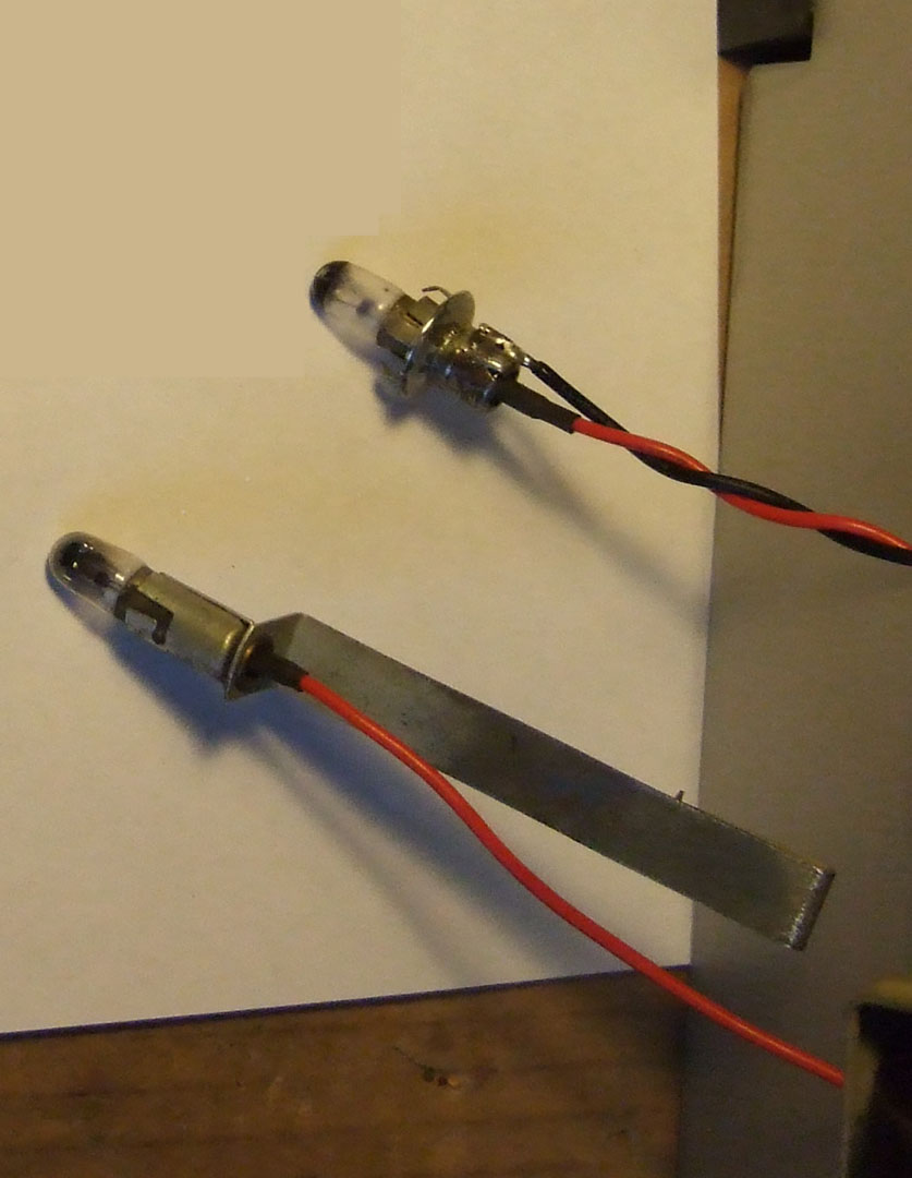
One thing that is different about this model is there is a power on indicator lamp that fits into a hole in the cabinet wood up front (top lamp in above photo). This socket is different in that it has some spring teeth that engage the wood to hold it in position securely. The mice had managed to cause corrosion on this socket similar to what they did on the chassis. After I managed to get the spring and original metal washer out of the socket, it took considerable effort to clean the corrosion out of the inside of the socket. For some reason, the washer did not want to move smoothly in the socket with the spring action. I had to do two things, polish the inside of the socket cylinder with some scotch-brite pad on the end of a screwdriver and filed down the OD of the nylon washer until smooth action was obtained.
All of the lamps are Tung-Sol No. 44 type. I may use 1847 lamps instead.
The front power indicator lamp is fed filament voltage after passing through a series resistor. The 40-200 schematic shows it to be a 10 ohm resistor. This one appears to be a 16 ohm resistor. I doubt there is any reason to use a different resistor than the 40-200 model.
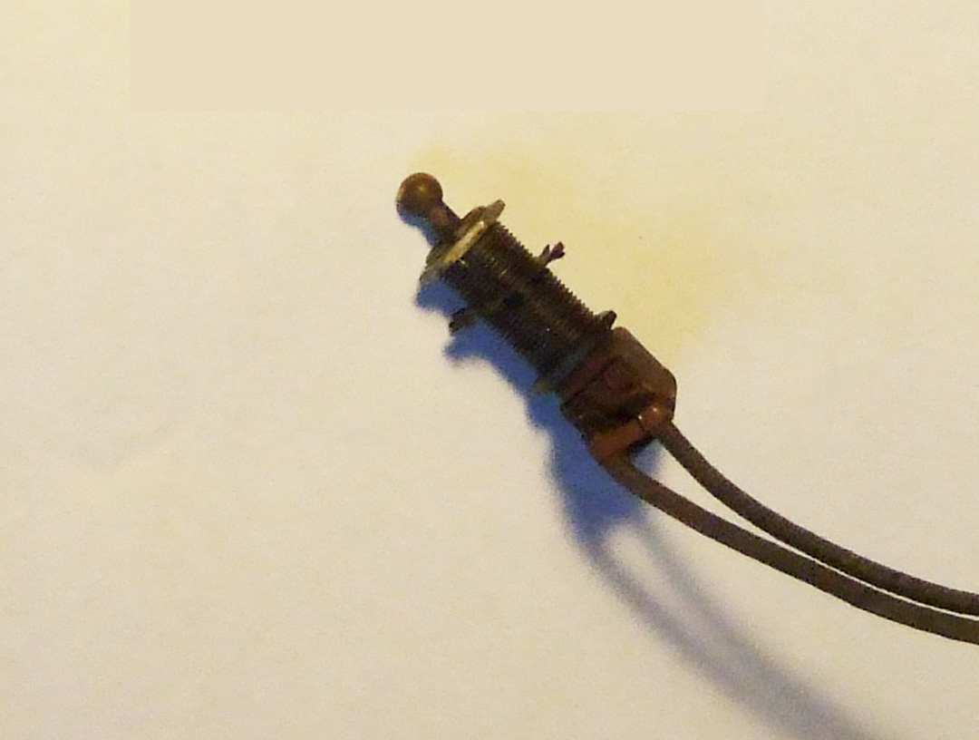
Next I need to find a new power toggle switch. It needs to have at least a 7/8 inch threaded shank to fit all the way through the 3/4 inches of wood at the front of the cabinet. I am pretty sure that is the way the radio was designed. There is no other on/off switch on the radio. The push-button controls only handle a phonograph RF tuned circuit and seven other AM broadcast station presets. The volume and tone controls have no switch on them. The OEM switch is hopelessly corroded from the mice and I do not trust it.
I may get the re-wired I.F. transformers connected back in circuit tomorrow.
Joe
(This post was last modified: 12-03-2013, 11:00 AM by Joeztech.)
Posts: 348
Threads: 48
Joined: Oct 2013
City: Tioga, Texas, USA
I remembered that I had the wiring harness from a Dodge van of 1970s era in the barn. I found it yesterday and found that it had two dial lamp sockets that were the same size as used on these Philco radios. They even had slide-on shield that direct the light beam to whatever side you desire. Don't overlook your local auto salvage yard as a source for such items.
Joe
Posts: 152
Threads: 11
Joined: Feb 2013
City: Dallas, TX
I just rebuilt those same type of lamp sockets in my 41-315X. fortunately my pilot lamp socket wasn't peed on. however, the spring action is a bit finicky. the existing washer in there seems to be sneaking past the indentation that's supposed to hold it in. did you use #6 washers filed down on the dial scale lamp sockets too? Fortunately, I used #4 ( I think) nylon washers and nylon sleeves I picked up from the local electronics shop to mimic the type of sleeve the older sockets used. switching to the rubber ones was not good for those of us trying to restore these 70+ years later.
Posts: 348
Threads: 48
Joined: Oct 2013
City: Tioga, Texas, USA
I think the main reason the power pilot lamp in my 42-201 had trouble with the movement of the washer/rivet contact movement was that there was corrosion on the inside of the socket. The sleeve part of the socket metal may have been manufactured with a slightly undersized ID too. The combination made movement of the washer/rivet assembly almost impossible at first. Using the Scotchbrite pad and screwdriver helped clean out the inside of the sleeve and I also lengthened the spring just slightly. It took repeated effort to get the corrosion out of the inside of the sleeve area. That combined with filing down the no. 6 nylon washer eventually got it working well. For the lamp sockets at the dial, the no. 6 washers and spring worked well the first try. They had no corrosion on the inside of the lamp socket sleeve.
I think the design of the lamp sockets ultimately does not need any indentation to keep the rivet/washer/spring combination in place. The lead wire coming out the back and the insertion of the lamp will take care of that. The designers and manufacturers may have thought it was important to do, but for our purposes it does not seem necessary and in fact actually makes the repair somewhat difficult in some cases.
I like your idea of the nylon sleeve inside the metal sleeve. That definitely provides a smooth and slick surface for the washer/rivet assembly to move inside of. Teflon sleeving would be a good item to try too. Teflon and nylon are both self lubricating. Teflon of course will stand high temperatures. It just shows how combining ideas can result in a better solution to problems when we all contribute.
Joe
Posts: 152
Threads: 11
Joined: Feb 2013
City: Dallas, TX
maybe I used #6.... I kind of wish I had written it down. I just bought the 2 I needed and said, "I'll never forget that"
Although I mentioned in in one of my videos, so I could go back and watch it. hehe
Posts: 348
Threads: 48
Joined: Oct 2013
City: Tioga, Texas, USA
Yes my memory is not so great for details either these days. I was mentioning using industrial type tubes in place of the 6V6GT tubes in my H-K A300 amplifier and instead of writing 7408 I wrote 7409. I went back and corrected the mistake. I try to write things down, and especially commit them to files on my computer which gets backed up frequently. That way I can check myself if I think to.
I did manage to find some 1847 lamps at Radio Shack in Sherman, TX and bought them. The radio had no. 44 lamps in it which take more filament current. The 1847 lamps only use 0.15 or 150ma of current from the filament string in the radio. They would also create less heat too as a result. As an ultimate choice I could always implement LEDs using a protection diode and series current limiting resistor for the LED, but then it would not be very original anymore. I mentioned above about the radio having a 16 ohm resistor instead of a 10 ohm resistor in the pilot lamp circuit. I finally got a schematic that showed that the actual value in a 40-200 model was 16 ohms, not 10 ohms as I read at first. This was due to a poor quality scan of the schematic I was using.
Joe
(This post was last modified: 12-16-2013, 06:12 PM by Joeztech.)
Posts: 152
Threads: 11
Joined: Feb 2013
City: Dallas, TX
I looked up your radio.. it's nice looking! you can also get 10 packs of 1847's @ pinball life. they're 2.50 a box. I swapped out the 44 in the pilot lamp for a triple LED red bulb and the band indicator with a quad warm white, super bright LED. even with the #239 bulb that the schematic calls for @ .35 amps wasn't bright enough, IMO. plus the 2 LED's take some of the load off the filament section of the PS. I am keeping the 44's in the dial and #239 bulb for the push button labels though. I'm really only ok with the harsh white LED light in some applications.
I've been get lamps from WJOE lately. He carries the lamps I need for my vintage HI-FI stuff (Japanese and European) weird bulb specs they used over there. plus the 239 bulbs (philco part 24-2141) he carries as well. Also 1866 (long life #44)
Does yours have the frosted pilot lamp (Philco part 34-2210) ? I couldn't tell from the pic if it was frosted or just darkened from age.
Posts: 348
Threads: 48
Joined: Oct 2013
City: Tioga, Texas, USA
The one that was in the socket was just darkened with age, not frosted. However, I have no way to know if it had been replaced some time in the past. I suspect that it was. There is supposed to be a lens or jewel for the pilot lamp to shine through. I think it was red. Apparently no one makes a replacement for these. Does your set have the lens/jewel?
Incidentally, I looked at the membership roster at VRPS and found you, but I do not show up there or in the new members list. I have filled in a new membership form and sent it back to VRPS in hopes that they can get it corrected.
Joe
Posts: 13,776
Threads: 580
Joined: Sep 2005
City: Ferdinand
State, Province, Country: Indiana
Joeztech Wrote:There is supposed to be a lens or jewel for the pilot lamp to shine through. I think it was red. Apparently no one makes a replacement for these.
A good solution is in this thread:
http://philcoradio.com/phorum/showthread.php?tid=7865
--
Ron Ramirez
Ferdinand IN
Posts: 152
Threads: 11
Joined: Feb 2013
City: Dallas, TX
look at my thread on the 41-315X (not the alignment one). I just posted two pics of the jewel I installed. it looks remarkably like the original. assuming yours also has the 3/8" hole. the original plastic ones, from what I've read in several places, dried out, deformed and crumbled to dust. Which is why they're missing 99% of the time.
anyhow.. I have 3 more of those, I can bring one to the next VRPS meeting. You just need to pop the neon guts out of it, possibly trim off 1/8-1/4" and it pops right in, nice and snug.
Posts: 348
Threads: 48
Joined: Oct 2013
City: Tioga, Texas, USA
Bret;
Thanks for that offer. I should be at the next meeting if all goes well. That certainly is a nice set you found. All the stars and planets must have been in alignment for you to find it due to the road construction!
There are still some applications for indicator lamps and neon types are long lasting. Lots of them used to be common in 110-125VAC applications too.
Have fun!
Joe
Posts: 348
Threads: 48
Joined: Oct 2013
City: Tioga, Texas, USA
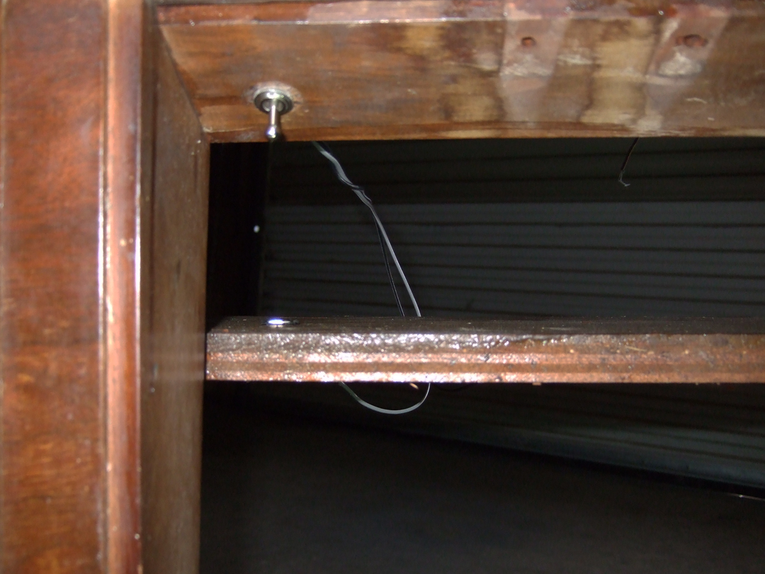
I showed the old AC switch in an earlier post. I finally received the new AC toggle switch from Ace Hardware, their item no. 3135746. It turned out that it was only 7/8" long in the shank area while the OEM Philco part was a full 1 inch long shank. However, I managed to get this one to work. I used a small keyhole saw and cut notches about 1/8" deep on either side of the hole it is to pass through. I used a 1/2 inch wide wood chisel to carefully remove the excess wood, then smoothed the resulting notch using a small rasp and flat file. When I finished I managed to seat the new switch and fasten it using no back-nut, just the front knurled nut that is the finishing item for fastening.
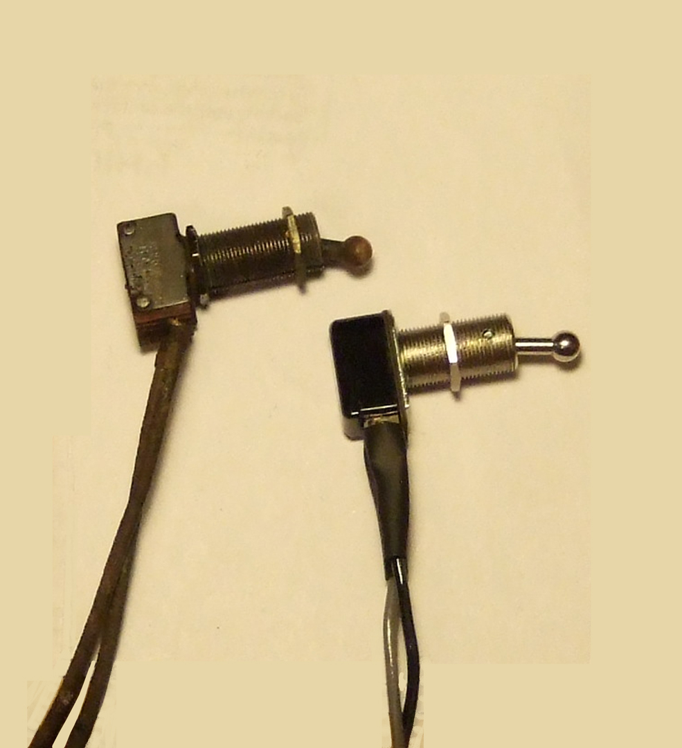
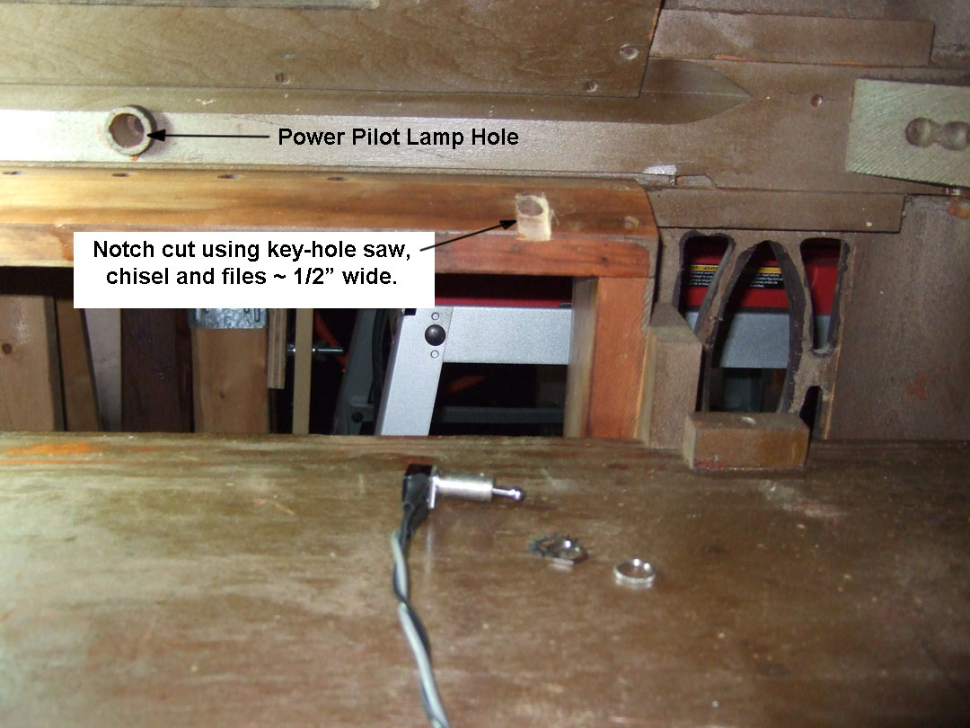
I used a gray wire and a black wire to wire up the switch using the same length wires as originally done by Philco manufacturing. The screws were removed from the terminals and the wires soldered to the lugs and heat shrink tubing added. The wires pass through the same chassis hole as the left hand dial lamp and pilot lamp wiring. Now to attach the pendant AC switch to the under chassis wiring. Its mounting spot is now ready to receive it when the chassis is reinstalled in the cabinet. The end result will work in the same position just like the original switch did.
Posts: 152
Threads: 11
Joined: Feb 2013
City: Dallas, TX
I know that feeling you get when you think you have the right part and it's just a smidge too short! I loathe having to make modifications to cabinets, even if they're inconspicuous. But I'm weird like that.
it looks really good!
the switch was messed up on the 41-315X as well. but it's a push-on-off switch that's riveted into the buttons assembly.
I threw caution to the wind and crossed my fingers.. I was able to get the case to break open right where I wanted it to, fix it and encase it in epoxy.
[Image: http://i1303.photobucket.com/albums/ag14...8b2c59.jpg]
[Image: http://i1303.photobucket.com/albums/ag14...36caad.jpg]
[Image: http://i1303.photobucket.com/albums/ag14...ae451f.jpg]
looks like you've got the cabinet back together?
Posts: 348
Threads: 48
Joined: Oct 2013
City: Tioga, Texas, USA
No, not yet. I have to get some poplar wood to re-manufacture the lower left base trim, put new plastic buttons on the bottom to protect floors. I also have to get new grill cloth for left and right panels and the center over the speaker. The grill cloth mounting panel is cardboard and it is warped from moisture exposure. I will have to make a new one with built-up poster board. At least I have the old one to use as a template. There is also some damage from termites at the lower left end of the front base trim. It is not as bad as the left side, so if I can get enough wood to make a new left lower piece for the side and part of the front I will be ready then to do some cabinet refinishing. There will be some veneer to make minor repairs to also. There are always a lot of details to take care of along the way.
You did a great job repairing that AC push-on-push-off switch. Thank goodness there are still some made almost identical to the old ones. I did discover that the Arrow company that made the original switch that Philco used on my radio is still around. They have some unusual switches that they make to supply the aircraft aftermarket repair businesses. Unfortunately anything related to aircraft carries a high price tag. The Ace switch was the closest to the original that I could find and was reasonably priced. The one downside of Ace Hardware is that you only have the choice of UPS delivery which is high cost. It would have been much more reasonable if they offered US Postal System delivery. I don't have to have real quick delivery.
Joe
Users browsing this thread: 1 Guest(s)
|
|
Recent Posts
|
|
1949 Motorola 5A9M
|
| bob
Nice work on battery . If you don't. Have terminals i have a few spares
Samsam — 02:12 AM |
|
1949 Motorola 5A9M
|
| hello mr Fixr,
for sure !!
I have some radios that I need to make some batteries for too.
Sincerely richardradiorich — 12:33 AM |
|
1949 Motorola 5A9M
|
| Dittos, sweet b on the battery. Love the "9 Lives" logo, remembered from my childhood. Other neat ones are t...MrFixr55 — 11:24 PM |
|
Philco 46-1209 strange behavior
|
| Hi Morzh,
Dunno if the AC EMI caps are an issue. I never liked the concept but never had an issue with these causin...MrFixr55 — 11:21 PM |
|
Philco 46-1209 strange behavior
|
| And no hum without the 7AF7? Not common but I am thinking heater - cathode short. This would introduce hum in this sta...MrFixr55 — 11:14 PM |
|
schematics
|
| Those filter caps in the cardboard tube are easy to restuff, especially the kind with the rolled over end. You don't hav...Arran — 09:56 PM |
|
Philco Model 16 wiring question
|
| If you have 5 wires, do this:
The wires that go to thick-wire wound winding are the filament.
If you do not know wha...morzh — 09:03 PM |
|
Philco Model 16 wiring question
|
|
I recently acquired a Philco Model 16 Code 126. I removed the power transformer to place heat shrink on some very bad...bobclausen — 08:23 PM |
|
1949 Motorola 5A9M
|
| Hello Bob,
That battery looks great nice job !
Sincerely Richardradiorich — 08:20 PM |
|
1949 Motorola 5A9M
|
| Yes, I plan to put a Velcro closer on the top.klondike98 — 07:28 PM |
|
Who's Online
|
| There are currently no members online. |

|
 
|


![[-] [-]](https://philcoradio.com/phorum/images/bootbb/collapse.png)


