Welcome Guest! Be sure you know and follow the Phorum Rules before posting. Thank you and Enjoy! (January 12) x

Thread Closed
Thread Rating:
  • 0 Vote(s) - 0 Average
  • 1
  • 2
  • 3
  • 4
  • 5

Protection jig for SS generator
#1

As I told before, I bought an HP sig gen. Before I use it, I decided to make a quick jig to protect it from those charges that sonetimes kill SS output, even when connected through a cap.

This is the generator (the bottom piece)
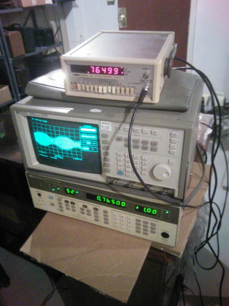
   

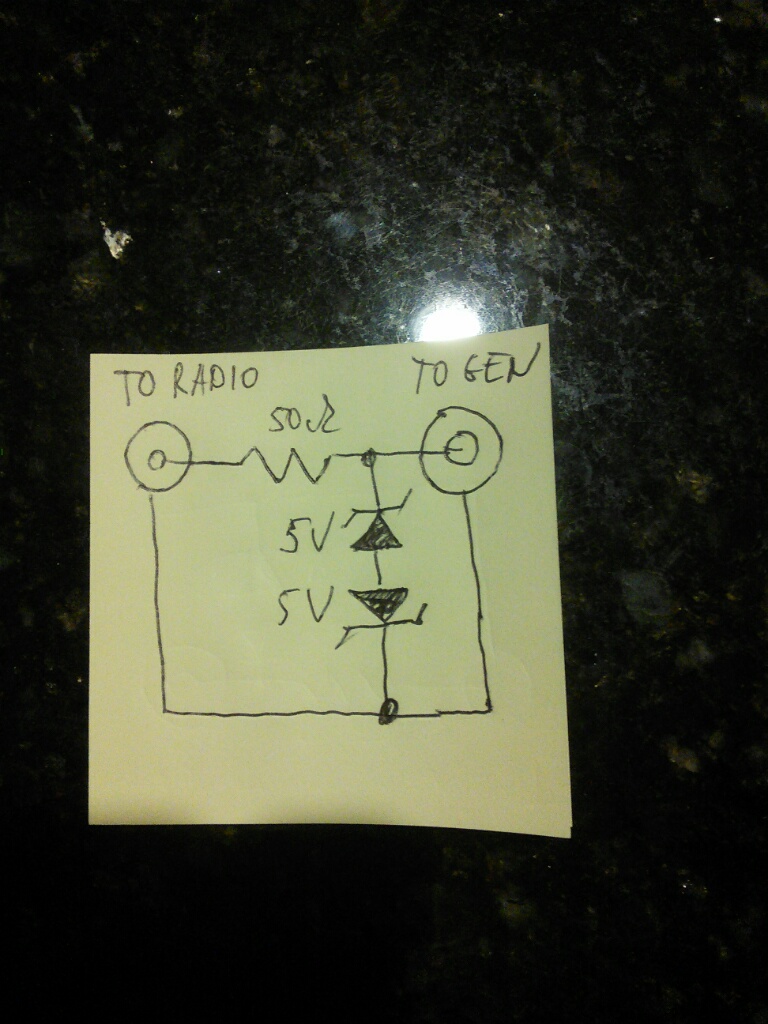
This is the sch of the jig

The resistor is small, can be from ohms to 20-50 ohm. The Zener is one part, back to back pair. The polarity doesn't matter, could be plusses or minuses out.  I had 5.6V ones.
The voltage is thus clamped at 5.6+0.7V=6.3V. Could be higher or lower. The output signal is 1V RMS or 1.4VPP so anything between 2V and 10V is ok.
   

This is the jig
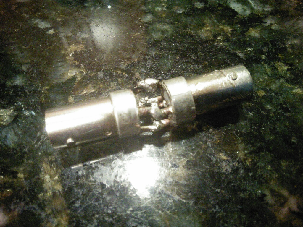


The zener and the resistor are small, SC-89-3 and 0603 respectively. But the connectors soldered back to back are so rigid that no effort is transferred to the small components inside.

People who do not drink, do not smoke, do not eat red meat will one day feel really stupid lying there and dying from nothing.
#2

Very neat Mike!

I don't hold with furniture that talks.
#3

Just bumping this up since Ron's Signal Generator thread was resurrected.

Thanks Mike!

John KK4ZLF
Lexington, KY
"illegitimis non carborundum"
#4

Yeah...imagine me soldering this with my shaky hands.....

I actually amazed myself this week, I designed a board that has to use very small components, the board itself (have to hold it in hands, no holder) - 0.5x1.8", and the components like SC-70-8, with pins 0.5mm (20 mils) from each other with the pin itself being 12 mils wide, with 8 mils space between them. Compared to that the 0402 resistors (40x20 mils) are gigantic.

Soldered the whole thing.

People who do not drink, do not smoke, do not eat red meat will one day feel really stupid lying there and dying from nothing.


Users browsing this thread:
[-]
Recent Posts
Philco 610B oscillator wiring
Thanks Terry. After checking my notes I think I recorded about -10v at the 6A7 G4/control grid. The screen grid (G3 &...Tubester — 05:59 PM
The list of my radio & TV collection!
Magical chords of forgotten melodies, old nostalgic music on an old radio... Saturday night blues on the Mid-Waves on an...RadioSvit — 12:20 PM
Philco 42-345 Restoration/Repair
Thank you MrFixr55 the issue with this radio is that the internal coil antenna is missing and there was a wire in its pl...osanders0311 — 11:34 AM
Philco 610B oscillator wiring
Regarding the oscillator circuit which is comprised of the 6A7's cathode, control grid, and screen grid. These elements ...Radioroslyn — 10:33 AM
Philco 42-345 Restoration/Repair
Hi OSanders, First off, welcome to the Philco Phorum where Phine Phamily-Phriendly Pholks Phull of Philco Phacts and P...MrFixr55 — 08:41 AM
Philco 42-345 Restoration/Repair
Today I've been reading through the site trying to learn more about this radio. I also soldered the lose power cord cabl...osanders0311 — 08:24 PM
Philco 610B oscillator wiring
Thanks David! I do have that same later prodution model 610 schematic. I've also studied the Philco service bulletins fo...Tubester — 08:12 PM
Philco 610B oscillator wiring
Some info from Beitmans says late production. David   David — 06:06 PM
Restoring Philco 96
Oh wow! Just found this thread.  Brings me back to early days on this phorum.  I did a 96 back in 2017.  Thread here: ...rfeenstra — 06:05 PM
Philco 610B oscillator wiring
Thanks for the replies. It's not the really the hum that I am after. Just trying to understand why only the shortwave ba...Tubester — 04:01 PM

[-]
Who's Online
There are currently 2288 online users. [Complete List]
» 2 Member(s) | 2286 Guest(s)
AvatarAvatar

>