Posts: 2,037
Threads: 367
Joined: Jun 2010
City: Dover, OH
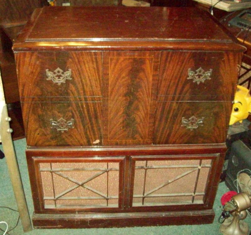
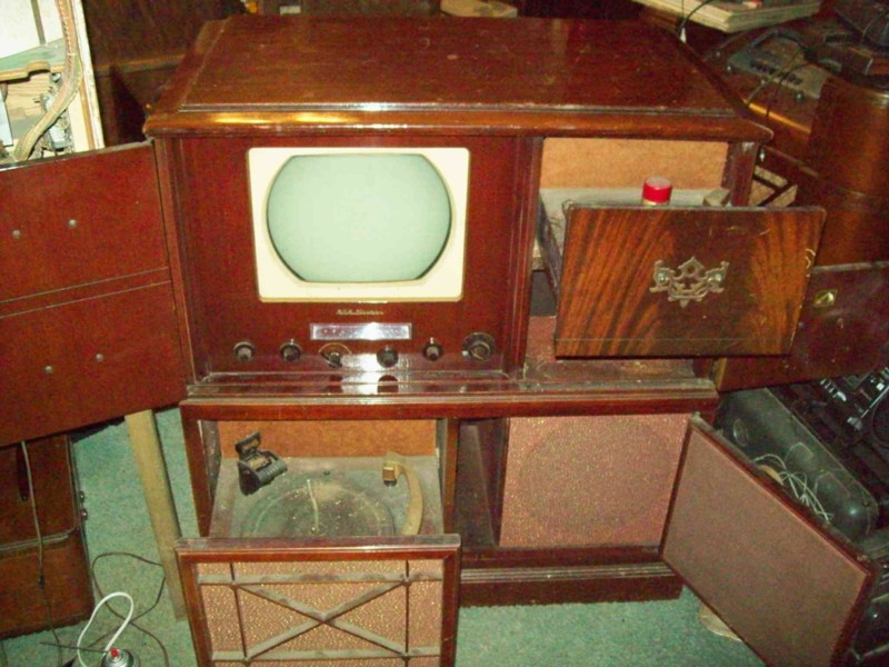
Well, here are a couple pictures of thise beast. It was about all my dad and I could do to get this thing up the steps and into the building. On the plus side it looks to be about compete with only a couple wires to repair. It also has an odd, one switch remote plugged into a socket on the back of the chassis. I've seen those sockets on other RCA TV chassis, but this is the first one I have found with something attached! There does seem to be a rare thing about this set, it appears that the CRT is attached to the chassis, meaning that the radio/TV chassis and tube can be pulled out in ONE unit. Heavy, yes, but it makes it easier to work on as the CRT and yoke can stay attached.


No matter where you go, there you are.
Posts: 7,305
Threads: 270
Joined: Dec 2009
City: Roslyn Pa
BBuster aint it!!!! It's good if the crt is fixed to the chassis my '50 16"RCA (KCS-47A) set it's fastened to the cabinet. Makes a little more of a challenge to service. I made up extension cables to power the crt and yoke. I learned that the insulation was a bit lacking for the anode lead, I won't tell you how I determined this. OUCH!!!!! I'll mention in passing if you are servicing it with the spkr/opt disconeted put the output tube (6K6?) Having no plate volt but retaining the screen grid voltage can damage the tube(s)
GL It's a fair amount of work to get it going properly.
Lots of paper caps some resistor and some micas mostly
in the sweep circuits.
Terry
Posts: 2,037
Threads: 367
Joined: Jun 2010
City: Dover, OH
You '50 RCA probably has that hard to find, metal 16 inch CRT doesn't it? I have another combination with one of those and spare parts. Used to have a spare CRT too until it decided to actually crack up the face while I had the CRT tester on it. One moment the tube neck was glowing, I heard a crack, saw a flash inside the tube and that was it. Luckily it didn't implode there in the living room! This one uses a 12LP4, which I have a possible spare of.
No matter where you go, there you are.
Posts: 7,305
Threads: 270
Joined: Dec 2009
City: Roslyn Pa
(04-20-2016, 09:13 PM)Jayce Wrote: You '50 RCA probably has that hard to find, metal 16 inch CRT doesn't it? I have another combination with one of those and spare parts. Used to have a spare CRT too until it decided to actually crack up the face while I had the CRT tester on it. One moment the tube neck was glowing, I heard a crack, saw a flash inside the tube and that was it. Luckily it didn't implode there in the living room! This one uses a 12LP4, which I have a possible spare of.
Yup it uses a 16GP4 metal cone crt. I got a spare and have '50 Zenith that uses too. Suppose to be lighter and cheaper to construct. You have to be careful when sticking your hand in the back of that set. It had a little paper tag attached with a string to the tuner which is near the back of the crt. When you fired it up the tag would float in midair because of the attraction from the anode voltage(about 12kv) on the back of the cone.
The 16" tube aren't real hard to find but 19" are. Have also heard that they can develop leaks at the glass/metal joint which renders the tube worthless. Too bad about losing the crt nobody is making replacements or rebuilding like in the old days. I guess these things are getting to be real dinosaurs!
So is this a do it your self project???
Terry
Posts: 4,928
Threads: 54
Joined: Sep 2008
City: Sandwick, BC, CA
From what I can recall most, if not all, of the non rear projection RCA TV sets from 1948-50 used a simplified and cheapened version of a 630 chassis, only retrofitting it to accept larger picture tubes as opposed to the 10BP4s that the 630s used. Unfortunately as the demand for TVs started to rise the build quality of RCA's TV sets also went down, it's not unusual to find sets with wiring errors and unsoldered tie points from what I read.
Metal coned picture tubes were an RCA development, I don't know how much cheaper they were to produce but on a larger screened tube that feature did reduce the weight. Unfortunately RCA also thought that using a metal cone was a good idea for their first production colour set, the CT-100, and more then half of those that still have the original tube have gone to air.
Regards
Arran


![[-] [-]](https://philcoradio.com/phorum/images/bootbb/collapse.png)


