Posts: 16,483
Threads: 573
Joined: Oct 2011
City: Jackson
State, Province, Country: NJ
Hi guys.
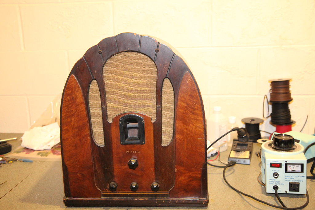
Decided to start on the 118.
This one I picked up on my way to get the 37-116 in MA I bough for Peter almost 2 years ago, in August 2014.
If anyone remembers, this was from the guy who all of a sudden decided not to sell it - he got offended by something. But eventually I got it.
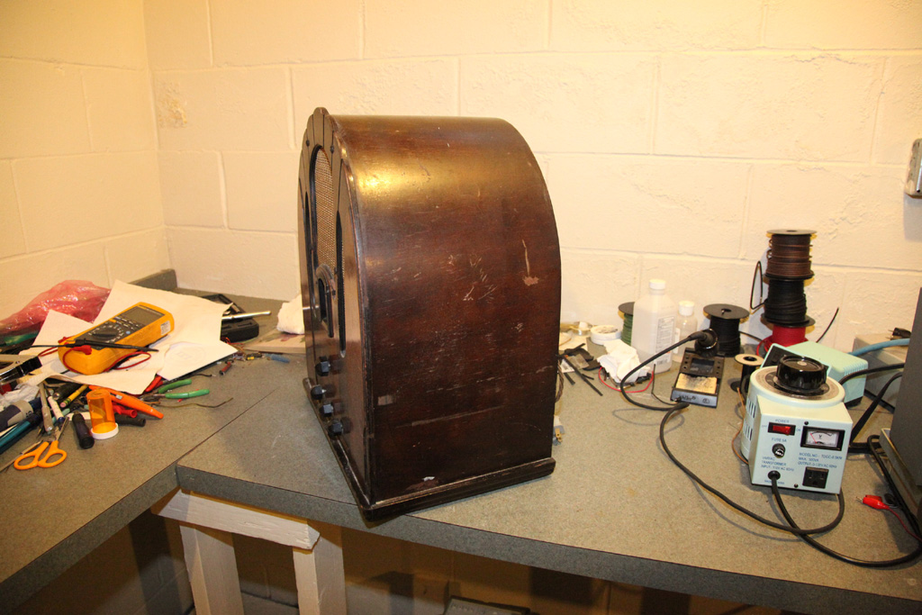
The cabinet is in decent shape: arch support in one place separates a bit but that's a gluing job. No bowing, pretty solid.
No screws hold the chassis in place from the bottom - it is held by the two brackets in the back. Don't know if that was the intent: the brackets are clearly factory but the missing screws I am not sure about.
Anyways, here are some photos:
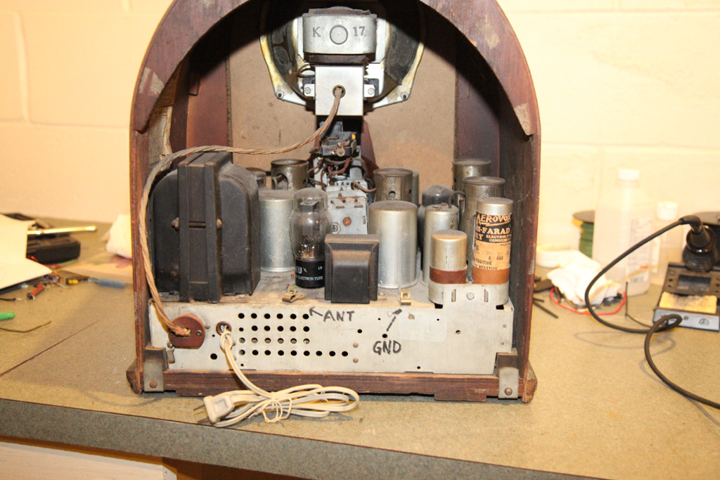
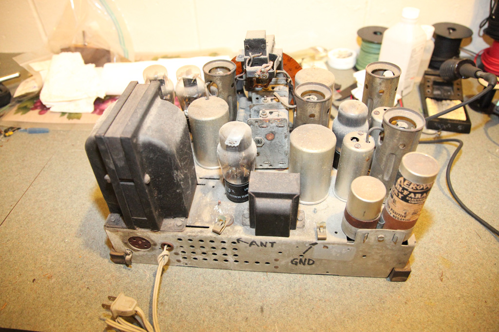
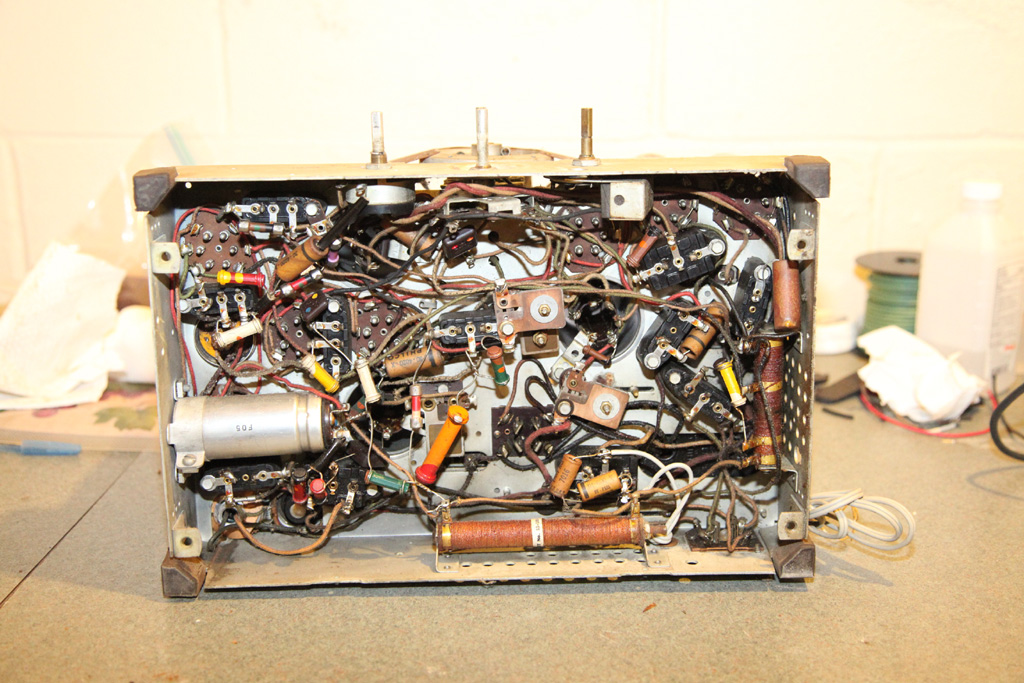
As you can see from the last photo, someone repaired it before: almost every backelite block has tubular caps soldered in parallel. The cord is not original  which is painfully obvious.
Very familiar picture: it is very much like the 18, which I restored 3 years ago or so.
Good news: the speaker has both the field coil and transformer good.
Well, this is it for now.
People who do not drink, do not smoke, do not eat red meat will one day feel really stupid lying there and dying from nothing.
Posts: 1,475
Threads: 69
Joined: Nov 2012
City: Kansas city, MO.
Looks like a clean rust free chassis and good cabinet, always a big plus. Never seen the rear chassis brackets before. interesting.
Posts: 16,483
Threads: 573
Joined: Oct 2011
City: Jackson
State, Province, Country: NJ
Yep.
Now I hope the RF coils and the interstage and power xfmrs are good.
The rest is easy.
People who do not drink, do not smoke, do not eat red meat will one day feel really stupid lying there and dying from nothing.
Posts: 599
Threads: 24
Joined: Jan 2014
City: Edmonton AB CA
My 118 has the same brackets.
Gregb
Posts: 16,483
Threads: 573
Joined: Oct 2011
City: Jackson
State, Province, Country: NJ
yes those are factory. Does yours have the bottom screws?
People who do not drink, do not smoke, do not eat red meat will one day feel really stupid lying there and dying from nothing.
Posts: 3,149
Threads: 56
Joined: Apr 2011
City: Lexington, KY
I've always liked the 118 cathedrals and that one looks like it is a very nice example. It should clean up well.
John KK4ZLF
Lexington, KY
"illegitimis non carborundum"
Posts: 5,164
Threads: 273
Joined: Nov 2012
City: Wilsonville
State, Province, Country: OR
Posts: 16,483
Threads: 573
Joined: Oct 2011
City: Jackson
State, Province, Country: NJ
Kirk! No pressure! But you will have to meet and beat the expectations here! Which are running high! 
People who do not drink, do not smoke, do not eat red meat will one day feel really stupid lying there and dying from nothing.
Posts: 16,483
Threads: 573
Joined: Oct 2011
City: Jackson
State, Province, Country: NJ
Howdy!
If anyone knows:
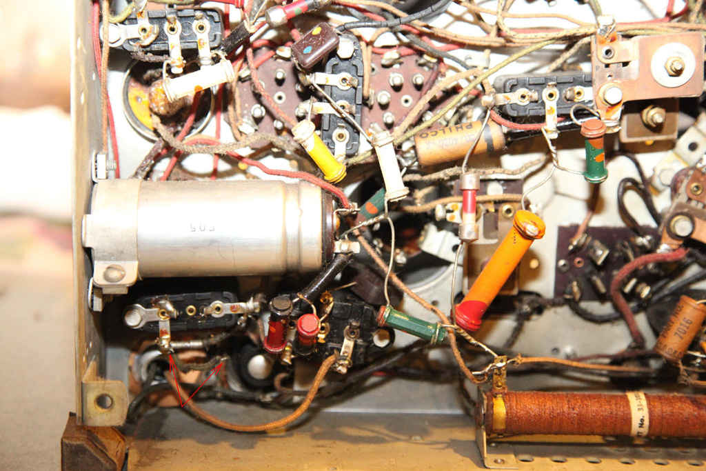
This here picture shows a free hanging ground wire that is attached to the ground lug of what looks like the cap #34, from the same point where the flex resistor #33 attaches to GND.
This is the way it was when I pulled it so I do not want to spend a whole lot of time investigating what's left with no GND. Plus to that the chassis was at some point repaired so it just might had happened that the wire was unsoldered (the forming looks like it was wrapped around a backelite cap's lug) and left this way.)
The soldering and the wire look original.
Anyone has a chassis to look at and see if it was there originally and where it goes to?
People who do not drink, do not smoke, do not eat red meat will one day feel really stupid lying there and dying from nothing.
Posts: 16,483
Threads: 573
Joined: Oct 2011
City: Jackson
State, Province, Country: NJ
Anyways,
As I just wrote in a separate post, there is an error in the sch in Rider's - a missing tie dot. Kinda obvious, and typical - same type errors we have seen in many Philco Rider's sch, like 90 and such.
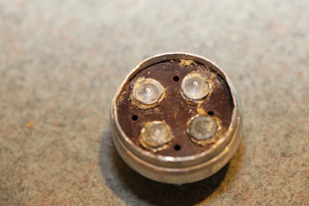
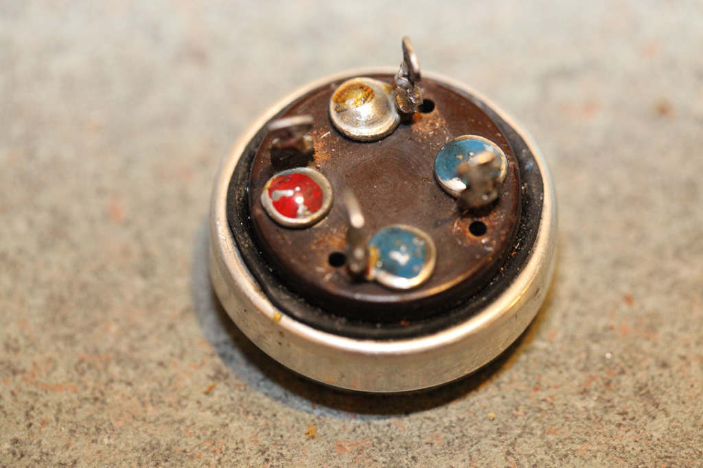
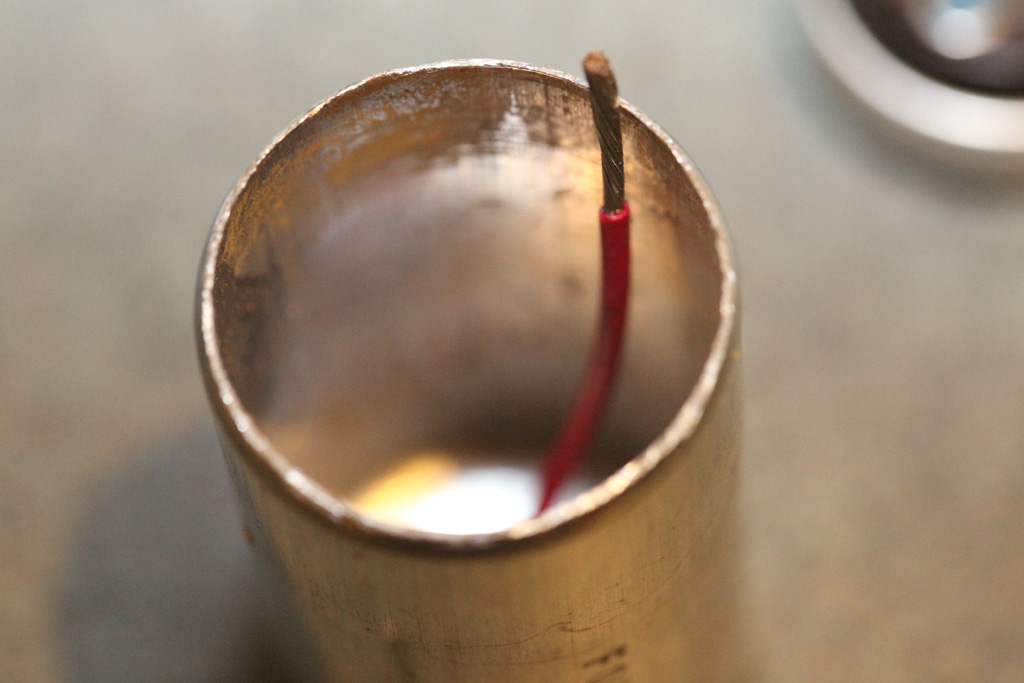
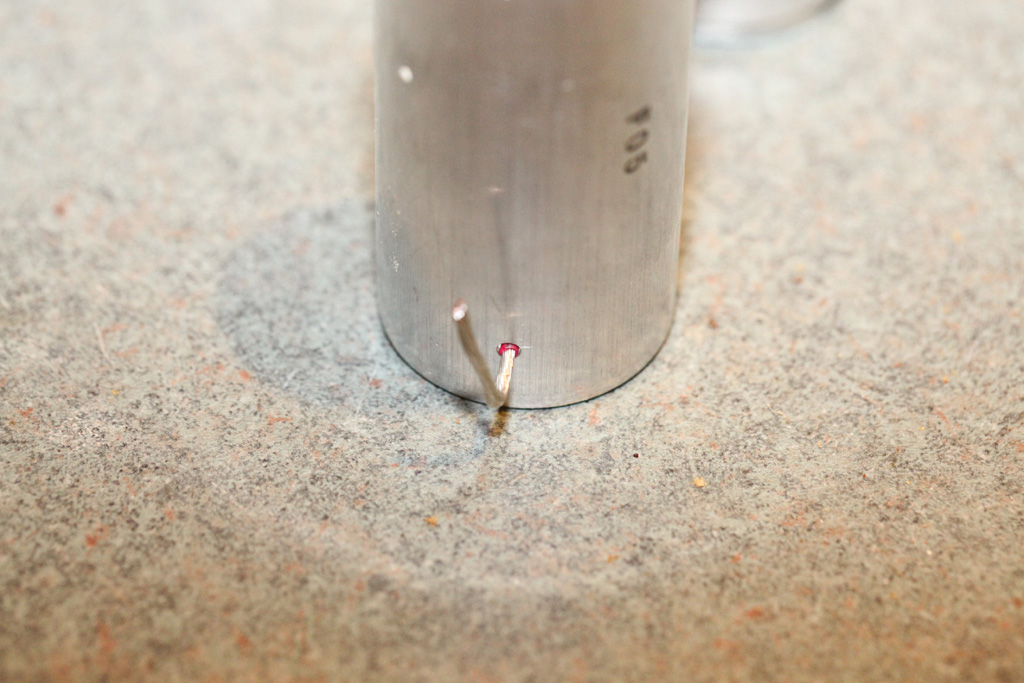
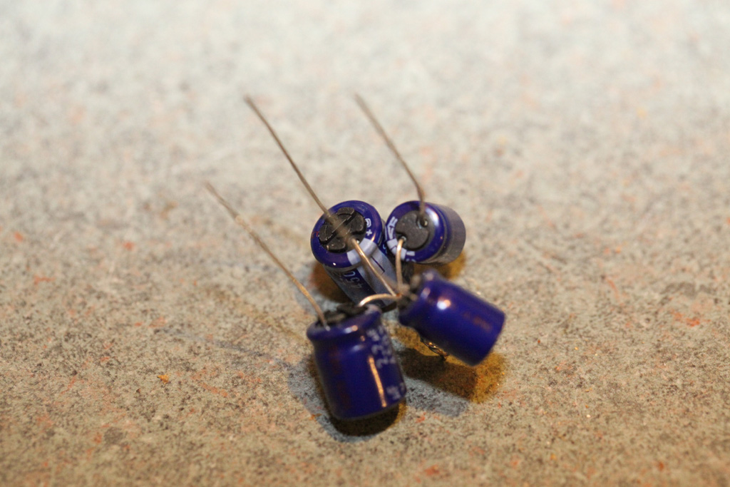
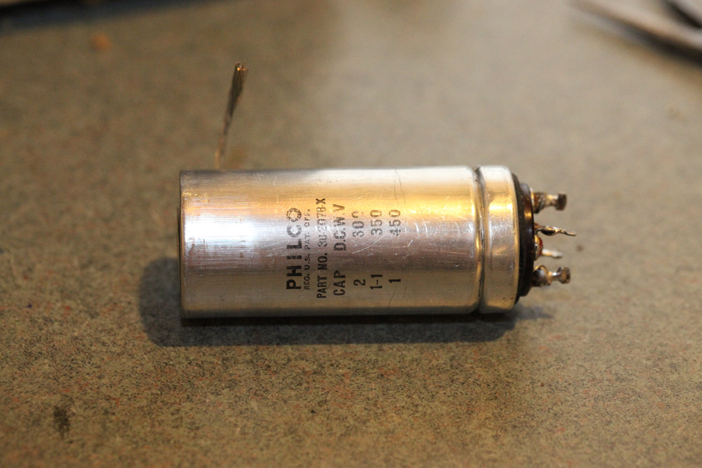
OK. I have rebuilt a quad lytic cap, 2x1uF and 2x2uF.
Here it is.
People who do not drink, do not smoke, do not eat red meat will one day feel really stupid lying there and dying from nothing.
Posts: 16,483
Threads: 573
Joined: Oct 2011
City: Jackson
State, Province, Country: NJ
People who do not drink, do not smoke, do not eat red meat will one day feel really stupid lying there and dying from nothing.
Posts: 16,483
Threads: 573
Joined: Oct 2011
City: Jackson
State, Province, Country: NJ
And finally.
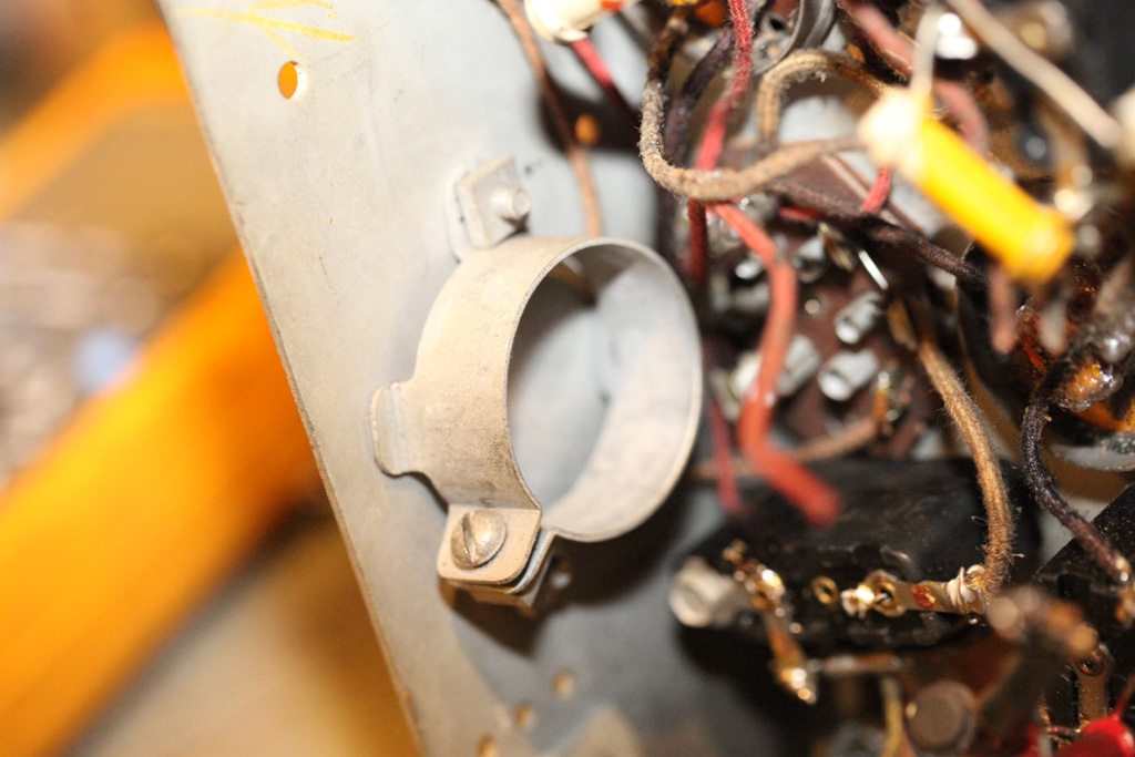
This tail will go inside the clamp providing the connection of the case to chassis. It won't be seen.
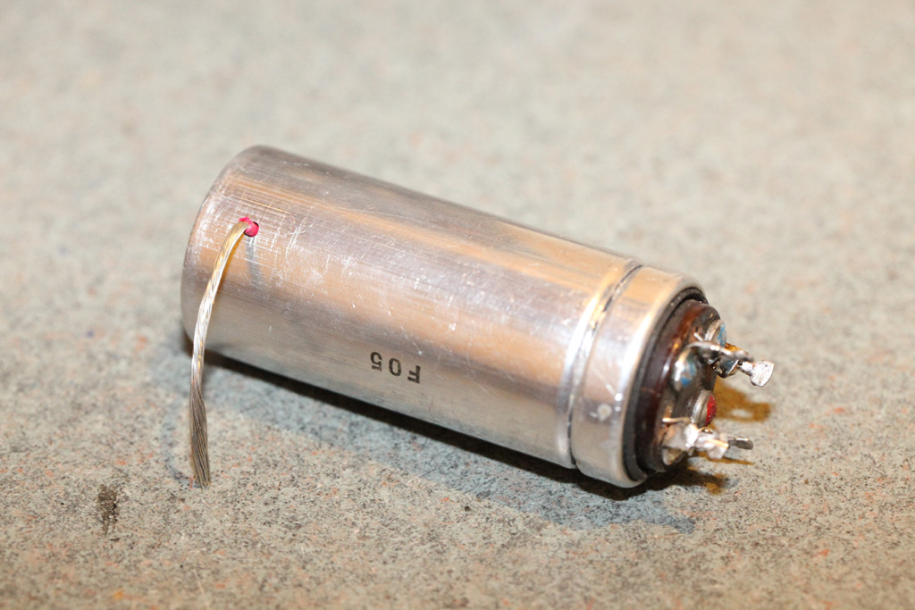
This is the clamp.
People who do not drink, do not smoke, do not eat red meat will one day feel really stupid lying there and dying from nothing.
Posts: 1,475
Threads: 69
Joined: Nov 2012
City: Kansas city, MO.
Nice job Mike. Did you figure out the unconnected ground wire you asked about ?
Posts: 16,483
Threads: 573
Joined: Oct 2011
City: Jackson
State, Province, Country: NJ
No. Methinks it is just a ground that was going somewhere befor it was unconnected during one of the repairs and forgotten about. After all it was not near anything it could short to so it lived happily many years after that, just hanging there.
Unless I find some use for it I will remove it.
I was tempted to look into my 18 chassis which is almost the same but I hate to start pulling it vrom the radio. Not that important.
People who do not drink, do not smoke, do not eat red meat will one day feel really stupid lying there and dying from nothing.
Posts: 16,483
Threads: 573
Joined: Oct 2011
City: Jackson
State, Province, Country: NJ
Continuing recapping.
I realized the 73 cap is dual. The way it was installed it wasn't. They installed a single 8uF electrolytic. And then I followed. The cap is supposed to be a dual 8uF/10uF cap, the latter decoupling the chassis to the rect neg. The famous"plus to chassis". Well, it is a low vokt guy, with value m ot critical so I installed an inconspicuous 33uF 100V cap in a convenient pkace, right between the pin of the low ohm bias divider and a backelite block cap's chassus bolt.
Another thing, the 42 driver shows a cap to chassis FROM G2 with nothing more. I think it is a mistake. In the chassis G2 is connected to the plate.
PS. Just checked the 18 sch. Yep the plate and G2 are conected.
People who do not drink, do not smoke, do not eat red meat will one day feel really stupid lying there and dying from nothing.
Users browsing this thread: 1 Guest(s)
|
|
Recent Posts
|
|
Need Help to ID this radio 11 tube Philco
|
| Yes the 16B as morzh pointed out. Specifically its the January 1935 model version of the 16B. There are a couple earli...klondike98 — 11:51 PM |
|
48-482 rear panel help
|
| Welcome to the Phorum, keithchip! How far you take a radio on cabinet restoration is a matter of personal preference. ...GarySP — 11:28 PM |
|
48-482 rear panel help
|
| I've recently finished the internal restoration of a locally purchased Philco 48-482. The cabinet is in ok shape except ...keithchip — 10:28 PM |
|
Need Help to ID this radio 11 tube Philco
|
| Welcome to the Phorum, Ken! Lots of help here for all of your restoration questions. Take care and BE HEALTHY! - Gar...GarySP — 07:59 PM |
|
Need Help to ID this radio 11 tube Philco
|
| Thank you.
I went to your online library and found 2 schematics.
I will download and compare to components!Ken D. — 06:31 PM |
|
Need Help to ID this radio 11 tube Philco
|
| It is a 16B tombstone.morzh — 06:13 PM |
|
Zenith H725
|
| David - sorry, I reread your post and finally saw THD - now the % figures make sense. Thanks for explaining.
The PSU...EdHolland — 06:06 PM |
|
Need Help to ID this radio 11 tube Philco
|
| Hi Everyone,
New member but have been reading this for awhile for tips!
Vaccum tubes were before my time so bear with ...Ken D. — 06:03 PM |
|
My Philco 37-116 Restore
|
| Thank you MrFixR55, I appreciate your comments very much. I do not detect much hum if any so I will be staying with the ...dconant — 05:15 PM |
|
My Philco 37-116 Restore
|
| Hi DConant
Yes, you can replace chokes with resistors. You do stand the risk of increased hum. the solution is to inc...MrFixr55 — 04:23 PM |
|
Who's Online
|
| There are currently no members online. |

|
 
|


 which is painfully obvious.


![[-] [-]](https://philcoradio.com/phorum/images/bootbb/collapse.png)


