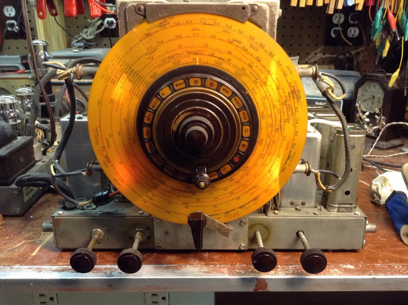
Got bored today so took my 37-690 apart
Posts: 76
Threads: 20
Joined: Oct 2010
City: Oskaloosa
State, Province, Country: KANSAS
Well one of the oscillator coils was bad in a 37-690 I have, so, a few weeks back I was bored and decided to dissect and repair the RF sub-chassis. I know, I know, some of you think a hole in your head would be better. Well I must say it was not as bad as I thought, considering this is the first one I have ever taken totally down before. Maybe ignorance is bliss!
I decided while I had the RF chassis out to replace all resistors out of spec, and replace any other caps missed from a previous repairman’s attempt. The RF chassis was really dirty with a lot of grease and grim all over down in the bowels of the contact switches. Since I plan to use this daily, I decide a good cleaning was in order. So I took each section completely down, cleaned and reassembled it. I mean I had already removed the RF Chassis so why not.
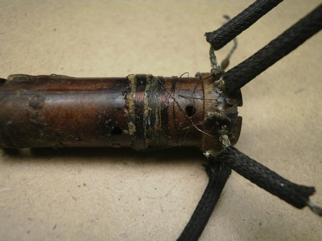
Well I did each section. Testing the coils and contacts as I went, I found the offending oscillator coil and replaced it with a good one from a 37-116 parts chassis I have laying around. The oscillator coil suffered from the dreaded green wire disease, maybe someday I may try to fix or rewind it, when I get real bored.
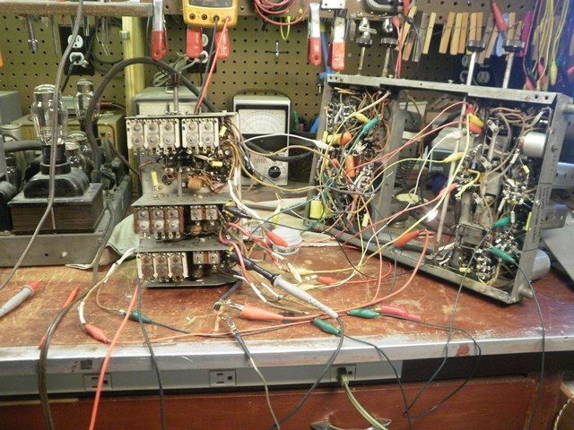
After I got the RF Chassis all back together, tested each stage with a signal generator and tracer, found a couple of miss wired coils on my part. I decided to see if I had ruined my radio forever. Well it works, and works well. I will put it back together; check out the rest of the chassis and power chassis. Repair the clarifiers and call this one good.
I figure a picture of how I tested the RF Chassis would show how crazy I am. 
Enjoy

Posts: 2,118
Threads: 112
Joined: Jun 2010
City: Medford OR (OR what?)
That is funny. I had never thought of hooking one up while disassembled. That would certainly have helped on the first one I worked on.
Was the 2nd band osc coil open? It has been on every one I have worked on.
"I just might turn into smoke, but I feel fine"
http://www.russoldradios.com/
Posts: 76
Threads: 20
Joined: Oct 2010
City: Oskaloosa
State, Province, Country: KANSAS
Yeah the primary is open. I peeled back the beeswax and removed the green corrsion to try and find the break. I found one but it looks like there is more.
My second 37-690 is good and works well. It looks like no one in a long time has been in there and done anything.

(This post was last modified: 11-20-2013, 12:12 AM by Skip.)
Posts: 1,475
Threads: 69
Joined: Nov 2012
City: Kansas city, MO.
Skip what a maze of wires. If I ever come across a 37-690 have to keep the problems you described in mind on what I might be getting into.
Good luck.
Posts: 2,128
Threads: 18
Joined: Oct 2008
City: Merrick, Long Island, NY
Dr F. Was Igor there to help out, and when will the storm prevail?
Just kidding, but you are far braver than I. The coil: Doesn't look that nasty from the picture, someone may have rewound one and might chime in.
Posts: 467
Threads: 31
Joined: Sep 2009
City: Lapeer
State, Province, Country: MI
Skip,
Great work. This isn't an easy task, but it is easier than it looks and worth the effort. I tore the RF sub-chassis out of my 37-650 because I was bound and determined that every cap in the radio would be replaced. However, it never occurred to me to test it BEFORE putting it back in! It worked just fine. You did a great job, be proud! Joe
Joe
Matthew 16:26 "For what does it profit a man if he gain the whole world, yet lose his own soul?"
(This post was last modified: 11-22-2013, 02:55 PM by Joe Rossi.)
Posts: 76
Threads: 20
Joined: Oct 2010
City: Oskaloosa
State, Province, Country: KANSAS
Thanks for all you comments. It really was not as bad as I thought. I took really detailed pictures and labled each wire from the RF chassis to the main chassis. I then printed the pictures, and highlighted the individual wires on the pictures. That way they were easy to trace on the photos later.
Well I have it all back together, and playing well. Still want to go through the power chassis and followup on the previous repairs. I look forward to getting it back into the cabinet.

Posts: 344
Threads: 38
Joined: Jun 2011
City: Tustin
State, Province, Country: California
Wow! Great job. What a good idea to test the sub chassis before putting it back together.
I don't know if I have that many test leads 
(This post was last modified: 11-24-2013, 02:37 AM by thirtiesradio.)
Posts: 7,303
Threads: 269
Joined: Dec 2009
City: Roslyn Pa
Bravo!!!
Nice job glad to see that it can work with the RF section out of the chassis and the interconnections aren't super critical in terms of lead length.
Terry
(This post was last modified: 08-15-2016, 07:48 PM by Radioroslyn.)
Posts: 79
Threads: 13
Joined: Feb 2014
City: Bristol, RI
Skip,
Great job. I just acquired a 37-690 and am dreading the disassembly of the RF deck. Are there any instructions out there for this task, or at the very least tips on how best to do it? I want to do this right but don't want to do something that can't be undone, by accident. Thanks!
Ted
Posts: 7,303
Threads: 269
Joined: Dec 2009
City: Roslyn Pa
Hi Ted,
Don't think there is a blow by blow description on the net. The front end is pretty much the same as the 37-116 and 37-675. The '38 model are similar but have a different trimmer layout. Try searching these models. The general consensus is to remove the dial assy to get it out of the way, remove screws holding the sub chassis, unsolder wires holding in till it comes out while photographing and marking where they went. Reverse to reinstall.
GL
Terry
When my pals were reading comic books
I was down in the basement in my dad's
workshop. Perusing his Sam's Photofoacts
Vol 1-50 admiring the old set and trying to
figure out what all those squiggly meant.
Circa 1966
Now I think I've got!
Terry
Posts: 79
Threads: 13
Joined: Feb 2014
City: Bristol, RI
(08-15-2016, 07:45 PM)Radioroslyn Wrote: Hi Ted,
Don't think there is a blow by blow description on the net. The front end is pretty much the same as the 37-116 and 37-675. The '38 model are similar but have a different trimmer layout. Try searching these models. The general consensus is to remove the dial assy to get it out of the way, remove screws holding the sub chassis, unsolder wires holding in till it comes out while photographing and marking where they went. Reverse to reinstall.
GL
Terry
Sounds pretty straightforward; I'll have a go at it some time this fall. Thank you; I'll probably take pix to either (a) show future techs how to do it or (more likely) show them what not to do 
Very excited to break into this radio. It's quite dirty and looks like it's been stored for many, many years. Crazy thing about it is it has not been touched, period. Not even the electrolytics have been touched. A quick test showed all power transformers, chokes interstage trasnformer field coils, etc., good. A nice bonus is the 6B4s appear very strong.
(This post was last modified: 08-15-2016, 08:22 PM by Diverted.)
Posts: 7,303
Threads: 269
Joined: Dec 2009
City: Roslyn Pa
(08-15-2016, 08:21 PM)Diverted Wrote: (08-15-2016, 07:45 PM)Radioroslyn Wrote: Hi Ted,
Don't think there is a blow by blow description on the net. The front end is pretty much the same as the 37-116 and 37-675. The '38 model are similar but have a different trimmer layout. Try searching these models. The general consensus is to remove the dial assy to get it out of the way, remove screws holding the sub chassis, unsolder wires holding in till it comes out while photographing and marking where they went. Reverse to reinstall.
GL
Terry
Sounds pretty straightforward; I'll have a go at it some time this fall. Thank you; I'll probably take pix to either (a) show future techs how to do it or (more likely) show them what not to do 
Very excited to break into this radio. It's quite dirty and looks like it's been stored for many, many years. Crazy thing about it is it has not been touched, period. Not even the electrolytics have been touched. A quick test showed all power transformers, chokes interstage transformer field coils, etc., good. A nice bonus is the 6B4s appear very strong. Will be an interesting project, you can do the blow by blow!
With a good robust set of 6B4's I may be able to hear in down here near phily!
When my pals were reading comic books
I was down in the basement in my dad's
workshop. Perusing his Sam's Photofoacts
Vol 1-50 admiring the old set and trying to
figure out what all those squiggly meant.
Circa 1966
Now I think I've got!
Terry
Posts: 76
Threads: 20
Joined: Oct 2010
City: Oskaloosa
State, Province, Country: KANSAS
Ted
As others have said, no step by step instructions on tearing one down. There is some info available on this Phorum and the other forum as well. Any questions, do not hesitate to ask. I sold that one to a club member, no worries I actually got them as a pair. Will be going through the second one this winter. When the 37-690 is done right, it is one of the best out there.
Take lots of pictures before and after and all will go smooth!
Posts: 79
Threads: 13
Joined: Feb 2014
City: Bristol, RI
I will!
I have a question, in planning stages at the moment. Several of the electroylitcs in this set are 475 or 500V. No problem, I'll order that rating ... except that I can't seem to find any 2 or 3uf caps with a 475 or above rating.
I could use 630v metallized polypropylene caps but as I plan to stuff the original cans, space might become an issue.
On the 2 and 3 uf caps, what should I do? Series two (4+4) and (6+6) electrolytics of a lower voltage rating? Or can I get away with standard 450v caps in the place of these 475s ...? Thinking not, but I have not done this set before and don't know.
Thanks!
(This post was last modified: 08-17-2016, 09:58 AM by Diverted.)
Users browsing this thread: 1 Guest(s)
|
|
Recent Posts
|
|
Philco 42-345 Restoration/Repair
|
| With regard to the speaker, unless the cone is so brittle that it crumbles as soon as you touch it I would try to repair...Arran — 04:07 AM |
|
Philco 42-345 Restoration/Repair
|
| That silver can capacitor is an aluminum electrolytic. You should replace it with an aluminum electrolytic with the valu...RodB — 11:46 PM |
|
Philco 42-345 Restoration/Repair
|
| Thank you Rodb and Gary for helping with clarification on these capacitors. Other than the Tiny 630volt one I'm not sure...osanders0311 — 10:17 PM |
|
1949 Motorola 5A9M
|
| Hello All;
I found the CMB41L down in the basement, it is definitely a 1950-51 model, the capacitors have date codes ...Arran — 07:48 PM |
|
Philco 42-345 Restoration/Repair
|
| Hi, all the caps I order, other than the electrolytics, are of the 630V rating. No worries on it being too high, and no ...gary rabbitt — 05:46 PM |
|
Philco 42-345 Restoration/Repair
|
| Hi, there's a lot to consider when designing these circuits so you shouldn't have a lot of concern when replacing caps. ...RodB — 02:03 PM |
|
Philco 42-345 Restoration/Repair
|
| I have ordered and received new caps for this radio and hope I've ordered the correct ones. I tried matching them to the...osanders0311 — 11:35 AM |
|
Philco newbie with P-1891-WA console questions
|
| Hello Jeff ,
Far as the Electrolytic capacitors go here is a list of parts.
that will work . I like using Nichicon and...radiorich — 09:50 PM |
|
Philco newbie with P-1891-WA console questions
|
| Well, I've been stumped at trying to get the first of 11 electrolytic capacitors. I got a schematic and have a list of t...Jeffcon — 07:54 PM |
|
Model 80 Antenna Issue?
|
| Thanks Gary and Rod.
I also found an article in the Philco Repair Bench under Service Hints and Tips, about installi...Hamilton — 12:32 PM |
|
Who's Online
|
| There are currently no members online. |

|
 
|


![[-] [-]](https://philcoradio.com/phorum/images/bootbb/collapse.png)


