Posts: 451
Threads: 85
Joined: Nov 2011
City: Cumming, GA
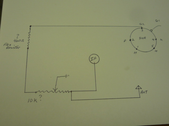
Here is a simple diagram of the volume ckt I have some unknowns
1. the 460ohm resistor the original was a flex resistor that was open. I found a section that had continuity and measured it then calculated that this is what it should be for the length, not sure if I'm right.
2 Vol pot was not original and was burned up I have used a 30k also with out any difference. Currently a 10k is this ok?
3 All the G2 pin 3 are tied in series
If I attach my ant to G1 of the 24A it plays great lots of stations.
What now?
Eric
Posts: 7,323
Threads: 270
Joined: Dec 2009
City: Roslyn Pa
Hey Eric,
Methinks your vc circuit should be closer to this:
http://www.nostalgiaair.org/pagesbymodel...008952.pdf
A lot of the old TRF sets the vc on one end is tied the ant and the other the the cathode circuit of the rf amps, wiper is grounded.
How it works is as you turn the vc down it lessens to resistance from the ant to the chassis esscenually shorting the ant to ground. And at the same time it's also increasing the resistance of the rf amps cathodes to ground raising the cathode voltage higher which lowers the gain.
Conversely turning the vc up allows more signal to pass though the vc from the antenna and brings the cathodes in the rf amps closer to ground which increases the rf gain.
Repeat after me, no IF no IF no local oscillator no local oscillator.
GL my friend
When my pals were reading comic books
I was down in the basement in my dad's
workshop. Perusing his Sam's Photofoacts
Vol 1-50 admiring the old set and trying to
figure out what all those squiggly meant.
Circa 1966
Now I think I've got it!
Terry
(This post was last modified: 10-05-2016, 06:02 PM by
Radioroslyn.)
Posts: 451
Threads: 85
Joined: Nov 2011
City: Cumming, GA
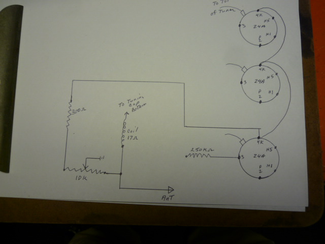
Ok I'm getting there but slowly I made a new print and hopefully corrected my mistakes
Posts: 7,323
Threads: 270
Joined: Dec 2009
City: Roslyn Pa
Now that makes much more sense. As you move the wiper to the left the volume increases and to the right it decreases.
Your gettin' it!!!! If you follow the wire that goes to the tuning cap's bottom it goes to one side of the stator, the other side of the stator connects to grid cap of the 24A.
When my pals were reading comic books
I was down in the basement in my dad's
workshop. Perusing his Sam's Photofoacts
Vol 1-50 admiring the old set and trying to
figure out what all those squiggly meant.
Circa 1966
Now I think I've got it!
Terry
Posts: 451
Threads: 85
Joined: Nov 2011
City: Cumming, GA
(10-06-2016, 06:22 PM)Radioroslyn Wrote: Now that makes much more sense. As you move the wiper to the left the volume increases and to the right it decreases.
Your gettin' it!!!! If you follow the wire that goes to the tuning cap's bottom it goes to one side of the stator, the other side of the stator connects to grid cap of the 24A.
So why do I get better reception if I connect the ant to the grid cap of the 24A than the ant terminal? I use about 25 ft of wire for the ant.
Thanks Eric
Posts: 7,323
Threads: 270
Joined: Dec 2009
City: Roslyn Pa
Because you are connecting the signal after the volume control well sort of. The vc doesn't have a lot of impact on the ant side of things till it is at a pretty low resistance (shorting the signal to gnd) On the cathode side the vc has much more affect by varying the gain of the rf amp tubes.
So the vc doesn't do much till it's all the down affecting the signal coming from the ant but you are bypassing that part of the vc. The vc will work some because it still can control the rf amps gain though the cathodes. If there wasn't a connection from the vc to the ant when you turned the set all the way down you would still hear some signals. With it hooked to the ant it eliminates this situation
Clear as mud right???
When my pals were reading comic books
I was down in the basement in my dad's
workshop. Perusing his Sam's Photofoacts
Vol 1-50 admiring the old set and trying to
figure out what all those squiggly meant.
Circa 1966
Now I think I've got it!
Terry
(This post was last modified: 10-07-2016, 01:58 PM by
Radioroslyn.)
Posts: 2,353
Threads: 92
Joined: May 2010
City: Clayton, NC
Neat early 30s set!! I have an Ozarka with a very similar cabinet.
Posts: 5,651
Threads: 56
Joined: Sep 2008
City: Sandwick, BC, CA
Well I have some news on my search for a schematic and model number for this set. First of all Riders has nothing on Halson sets produced prior to the 1933 model year, although some are similar electrically also being five or six tube TRFs. So I had a look in an RCA guide book that covers the chassis/tube layouts of sets produced from 1922-1935, the closest set that I could find based on the chassis layout was a model 510 from 1932, but it used a type 47 as a power output not a type 45, and I think it only had five tubes. So clearly this Halson is from the 1932 model year, but what is not clear is whether it is a model 510 from a different production run (perhaps an early model), or a completely different yet undocumented model. Unfortunately the 1932 Halson models are not listed in riders so I could not find a schematic of the model 510, which would have been useful in spite of the different power output tube, so the schematics linked to earlier are the best you can hope for.
Regards
Arran
(This post was last modified: 10-11-2016, 04:22 AM by
Arran.)





