Posts: 1,475
Threads: 69
Joined: Nov 2012
City: Kansas city, MO.
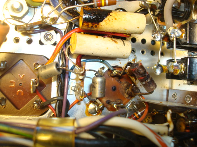
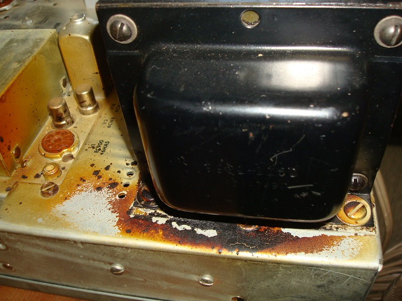
Here is some pics Ron and anyone else that might be interested. Putting it here cause I'll probably be needing some assistance in the near future.
It looks promising. I might order the complete rebuild kit from Jim McShane and do it up right. Also lot easier than trying to figure out all the components I would need.  [Image: http://i1336.photobucket.com/albums/o654...2xwvse.jpg
] [Image: http://i1336.photobucket.com/albums/o654...clncdc.jpg]
[Image: http://i1336.photobucket.com/albums/o654...1nyery.jpg] [Image: http://i1336.photobucket.com/albums/o654...vuoqns.jpg]
It has all fisher tubes in it. Guess will see if they test good.
[Image: http://i1336.photobucket.com/albums/o654...9ugq1t.jpg]
next step pull the bottom cover and see how it looks.
Posts: 1,114
Threads: 14
Joined: Feb 2013
City: Irvington, NY
I would not rush into replacing parts unnecessarily.
The caps are most likely already ceramic, or Mylar film as they began to be used around 1960 or so. Some of the existing caps are better quality than what you can buy today. I have a Fisher 400 running on all its original parts without any problems at all.
Download the service manual and check the parts list first. If they are listed as ceramic or Mylar I would definitely leave them alone. The nice thing about your receiver is that it is most likely completely original and untouched.
One thing I would definitely check and possibly replace is the selenium bias rectifier. If you lose negative bias on the output tubes they will cook and put excessive load on the power supply.
You can find the manual here: http://www.vintageshifi.com/repertoire-pdf/Fisher.php
(This post was last modified: 02-11-2017, 12:27 AM by Mondial.)
Posts: 1,128
Threads: 78
Joined: Jan 2014
City: Annapolis, IL
Probably don't need to mention this, but do replace the electrolytics. I do want to say that is a very nice system! I am glad to see it went to one of our members and not on Ebay in pieces. I look forward to reading about your restoration.
If I could find the place called "Somewhere", I could find "Anything" 
Tim
Jesus cried out and said, "Whoever believes in me , believes not in me but in him who sent me" John 12:44
(This post was last modified: 02-11-2017, 10:50 AM by TV MAN.)
Posts: 1,475
Threads: 69
Joined: Nov 2012
City: Kansas city, MO.
Thank you Tim. I look forward to getting this one playing soon. The Ecaps I count 14 total that's counting the multi cans as individual caps inside.
Mondial that is sage advice about not shot gunning the receiver. I'll not do that.
What is your opinion of just changing the Ecaps/ the rectifier, and the 4 coupling caps C87-89 on schematic to the output tubes and adding 4- 10 ohm 1/4watt resistors from the output tubes to ground? I've seen this recommended on several threads about the 800B to protect the tubes.
I checked the transformers last night and there okay.
Under chassis looks untouched.
[Image: http://i1336.photobucket.com/albums/o654...xfvgq3.jpg]
Posts: 1,114
Threads: 14
Joined: Feb 2013
City: Irvington, NY
It would not hurt to replace the four coupling caps with high quality 630V polypropylene film, and add fusible metal film resistors to the cathodes of the output tubes.
The seller wrote in the listing that the unit was in working condition. Have you powered the receiver up at all? I have a feeling it will work as is if you bring it up slowly with a variac to reform the electrolytics. It would be good to know if you have any existing problems before replacing any parts.
If it was mine, what I would do is first check for any shorts on the B+ supplies. Then remove the output tubes and monitor the output of the B+ supply as you bring up the AC line voltage slowly over the course of an hour or so. Stop when the B+ supply reaches about 250V. Make sure that none of the electrolytics is getting warm and if any are stop and shut it down.
If you get to this point without problems, check the negative bias supply at the negative can terminal of C98 and make sure you have negative voltage at that point. If it is ok then I would reinstall the output tubes, connect speakers and again bring up the AC voltage slowly until your B+ supply reaches 350 V. Make sure there is at least -22 V at the can of C98. At this point it will either work, or you have existing problems.
This is the procedure I use with any tube equipment built after the 1950's before changing parts.
Posts: 15,813
Threads: 553
Joined: Oct 2011
City: Jackson, NJ
Resistors are likely to be good, after all it's 50s. Likely not have to be touched.
Electrolytics.....they are always degraded and though could possibly be reconditioned, for a high quality audio I wouldn't. For a smaller radios it's probably fine.
People who do not drink, do not smoke, do not eat red meat will one day feel really stupid lying there and dying from nothing.
(This post was last modified: 02-11-2017, 12:31 PM by morzh.)
Posts: 1,475
Threads: 69
Joined: Nov 2012
City: Kansas city, MO.
I did power it up for very short time maybe 2 minutes before removing the chassis. It played with distortion in both speakers and the right speaker was very low with balance control equal. It did get somewhat louder when balance was turned to right channel only.
The stations came in where they should be on the dial and all lights were working and it changed btwn. FM and AM.
That's all I did and shut it off.
I will do what you advise. Can I use my 8ohm bookshelf speakers while working with it on the bench safely?
Posts: 1,114
Threads: 14
Joined: Feb 2013
City: Irvington, NY
It sounds like you may have no negative bias on the output tubes. It has already been powered up so it does not appear to have any shorts.
Then before doing anything else, first connect your meter between negative of C98 and ground. Apply full line voltage momentarily so you can get a reading. If its less than 22-24 volts negative then do not operate the receiver until the bias supply is repaired.
(This post was last modified: 02-11-2017, 12:46 PM by Mondial.)
Posts: 1,475
Threads: 69
Joined: Nov 2012
City: Kansas city, MO.
Can I use my 8ohm bookshelf speakers while working with it on the bench?
Posts: 1,114
Threads: 14
Joined: Feb 2013
City: Irvington, NY
Sure, no problem. Always have a speaker connected when testing, as tube amps do not like being driven without a load.
When you check the bias supply as I mentioned above, plug in the receiver until you get a stable reading. The bias supply also powers the filaments of the phono preamp tubes and the tubes need to be warmed up 30 seconds or so to get an accurate reading.
Posts: 1,475
Threads: 69
Joined: Nov 2012
City: Kansas city, MO.
Did the power up as and took reading on c-98 neg. to chassis. I get -15.1 volts. I had line voltage at 115v and it was drawing 2amps. Band set on FM. I tested all the tubes and the 2-12at7 tubes in MPX section were bad. Replaced them before the test.
The test speakers I had hooked up played clearly and balance control was smooth btwn left and right.
Should I replace anything else or just the parts recommended so far and then address the bias issue?
Thanks for helping on this.
Posts: 1,114
Threads: 14
Joined: Feb 2013
City: Irvington, NY
Address the bias issue before anything else. The coupling caps certainly can wait, as the originals are the equivalent of Sprague orange drops and are most likely fine as is.
Bias supply at -15 V is a problem as it will make the output tubes draw excessive current. The selenium rectifier is the cause and you can replace it with four silicon rectifier diodes on a terminal strip, or a packaged bridge rectifier like this:
http://www.ebay.com/itm/BR-62-Full-Wave-...xy2O1SZ~8v
In the meantime until you can replace it, connect a 1K resistor across R126 (5.6K) to increase the bias at the output tube grids to the proper value.
You want at least -14.5 V at each of the output tube grids to protect them.
(This post was last modified: 02-11-2017, 05:50 PM by Mondial.)
Posts: 1,128
Threads: 78
Joined: Jan 2014
City: Annapolis, IL


Further explanation needed?
If I could find the place called "Somewhere", I could find "Anything" 
Tim
Jesus cried out and said, "Whoever believes in me , believes not in me but in him who sent me" John 12:44
(This post was last modified: 02-12-2017, 03:39 PM by TV MAN.)
Posts: 1,475
Threads: 69
Joined: Nov 2012
City: Kansas city, MO.
While waiting on parts so I can proceed with the chassis. I figured I'd pull the speaker covers off the cabinet and have a look at what is inside.
[Image: http://i1336.photobucket.com/albums/o654...bblkys.jpg] [Image: http://i1336.photobucket.com/albums/o654...cntux2.jpg] Left and right cross overs? I'm newbe at speaker systems
[Image: http://i1336.photobucket.com/albums/o654...xsbo50.jpg]
[Image: http://i1336.photobucket.com/albums/o654...a2ltfv.jpg]
Both speakers look okay from backside.
Are the metal covered cans the tweeter and mid range?
[Image: http://i1336.photobucket.com/albums/o654...j387ps.jpg] Each speaker has an adjustment on the back panel.
What are these for exactly?
[Image: http://i1336.photobucket.com/albums/o654...mtd4zd.jpg]
One final pic. of left side.
[Image: http://i1336.photobucket.com/albums/o654...yoin4y.jpg]
Tim that picture you posted sure looked ugly. Did that happen to one of yours?
Posts: 13,776
Threads: 580
Joined: Sep 2005
City: Ferdinand
State, Province, Country: Indiana
Mike
Yes, those are crossover networks. You will want to replace the electrolytics with film caps from Parts Express.
Yes, the midrange and tweeter speakers are inside the cans.
The wirewound controls are L-pads. R1 on your speaker system schematic diagram (last page of your service manual). They control the loudness of the midrange speakers and the tweeters.
--
Ron Ramirez
Ferdinand IN
Users browsing this thread: 5 Guest(s)
|
|
Recent Posts
|
|
HiFi (Chifi) tube amp build - but my own design.
|
| And so does a barber shop quartet. mmmmmmRodB — 03:54 PM |
|
Shadow Meter Bulb
|
| I did try an LED bulb in place of the original but wasn't impressed with the amount of light on the dial. Seems like it ...RodB — 03:51 PM |
|
HiFi (Chifi) tube amp build - but my own design.
|
| Tim
Would mounting he transformer vertically change the hum, if used without additional parts?
Also, in these amps...morzh — 02:25 PM |
|
Shadow Meter Bulb
|
| Gary
I doubt it would introduce any noise. We use similar lamps for the panel indication, 12V AC lamps: they are LEDs...morzh — 02:15 PM |
|
Shadow Meter Bulb
|
| Not sure if anyone has tried this but there are 6.3 volt miniature lamps in bayonet and screw-in base options available ...GarySP — 11:31 AM |
|
Shadow Meter Bulb
|
| Any 6.3 volt pilot light will work. I would use the brightest one I could find in my workroom. Be sure the dial is clean...RodB — 10:45 AM |
|
HiFi (Chifi) tube amp build - but my own design.
|
| Tim,
nice write up and thanks for sharing !!
Sincerely Richardradiorich — 02:47 AM |
|
HiFi (Chifi) tube amp build - but my own design.
|
| Well, this was a real "Hum-Dinger" :lol: ! This will be kinda long, but hopefully it will help others having t...TV MAN — 01:55 AM |
|
Shadow Meter Bulb
|
| Phorum members, I am trying to find the bulb # for PHILCO Shadow Meter part number 45-2180 that is from a 37-640 chassis...georgetownjohn — 06:53 PM |
|
Philco 41-608 changer coupler
|
| 3D-printing...short of machining, of course.
Or molding.morzh — 05:20 PM |
|
Who's Online
|
There are currently 6430 online users. [Complete List]
» 1 Member(s) | 6429 Guest(s)
|
|
|

|
 
|


![[-] [-]](https://philcoradio.com/phorum/images/bootbb/collapse.png)


