Posts: 1,531
Threads: 242
Joined: Sep 2012
City: West Bend, Wisconsin
Working on what I thought would be a fairly simple one band, 5 tube radio. It's been not so simple so far...
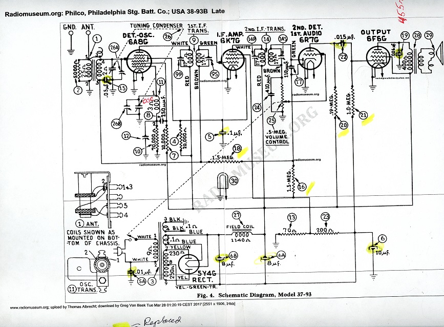
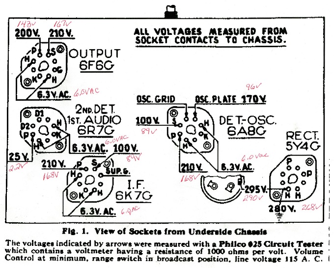
After checking all the tubes, doing a complete recap, and changing the resistors that were way out of tolerance, I'm left with a radio with very low volume with the pot wide open. I even replaced the volume control with a new 500K as per the schematic to no avail. My voltages are rather LOW (unfortunately the schematic doesn't list many voltages other than for plates) and I'm wondering if someone here could take a look at the numbers and perhaps point me towards what the culprit of the low volume may be? I'm working off of the 37-93 schematic, which most all sources online seem to indicate is the same as the 38-93. Just to be sure I'm ordering a set of 38-93's from Chuck. When I touch the grid caps of the tubes with the soldering iron I get a low buzz. It should be a whole lot louder. Ditto for the center tap of the volume control...very low volume buzz. The audio output transformer checks out at 455 ohms. I'm only getting 2 ohms on the 6R7 however (well, 2.2) but it should be 25 volts.


Greg V.
West Bend, WI
Member WARCI.org
Posts: 7,296
Threads: 268
Joined: Dec 2009
City: Roslyn Pa
Did you put #6 in backward???? + goes to the chassis - goes to #23.
When my pals were reading comic books
I was down in the basement in my dad's
workshop. Perusing his Sam's Photofoacts
Vol 1-50 admiring the old set and trying to
figure out what all those squiggly meant.
Circa 1966
Now I think I've got!
Terry
Posts: 1,531
Threads: 242
Joined: Sep 2012
City: West Bend, Wisconsin
That was my first thought but no, I have it in as you described. I knew it was just the opposite of the two 8 mfd's.
Greg V.
West Bend, WI
Member WARCI.org
Posts: 1,531
Threads: 242
Joined: Sep 2012
City: West Bend, Wisconsin
Now there's a discrepancy between the parts list and the schematic with regards to #16 and #18. On the schematic it says 1.5 MEG ohm but on the parts list it just says 1.5 ohm. The two resistors that were in each measured 2.3 MEG ohm, so I replaced them with two 1.5 MEG's.
Greg V.
West Bend, WI
Member WARCI.org
Posts: 16,476
Threads: 573
Joined: Oct 2011
City: Jackson
State, Province, Country: NJ
Your plate voltages are way low.
1. Is the speaker FC 1140 OHM?
2. Are 13 and 23 resistors good?
4. Is 6F6 running hot? Anything else is too hot?
Your 5Y4 out seems ok but then the plates are low, might mean excessive consumption.
People who do not drink, do not smoke, do not eat red meat will one day feel really stupid lying there and dying from nothing.
Posts: 4,862
Threads: 54
Joined: Sep 2008
City: Sandwick, BC, CA
The plate resistor on the 6R7 says .19 meg on the schematic, which is 190,000 Ohms, sort of a weird value, if it was swapped with something close to 19 meg that would explain the low plate voltage on that tube.
Regards
Arran
(This post was last modified: 04-04-2017, 04:03 AM by Arran.)
Posts: 358
Threads: 4
Joined: Aug 2015
City: Monteith, Ontario CA
Just a thought .... All the B+ readings are low, except at the rectifier .... in other words, on the rectifier side of the field coil the voltages are ok and on the radio side of the field coil they are all uniformly low. My first suspicion would be a defective field coil. Maybe try a quickie test of paralleling the field coil with a 1K resistor, just for a second to see if the volume improves. Alternately, you could stick a DC ma meter in series with the B+ coming from the field coil to see what sort of current the set is drawing. If it's too high you will end up with a voltage drop such as you have.
(This post was last modified: 04-04-2017, 07:39 AM by John Bartley.)
Posts: 1,114
Threads: 14
Joined: Feb 2013
City: Irvington, NY
Yes, I agree with Arran that there is a problem in the 6R7 circuit. Double check that resistor 20 is around 190K, and there is full B+ voltage on one side of it.
The 6R7 tube could also be bad. This tube operates with bias derived from the AVC circuit, so the voltage on the plate should change as you tune in a strong station and you vary the volume control. The plate voltage should rise with the strength of the received signal and increasing volume control setting.
Posts: 44
Threads: 4
Joined: Dec 2013
City: Freeport, LI, NY
Agree with John on this....
Follow the B+ from the FC to the plate of the 6F6. You have to check the FC for resistance as well as the primary of the OPT. These are static tests. The OPT should measure 400 ohms +/- 10%. The FC 1140 ohms +/- 10%. Another check would to make sure the 6F6 isn't shorting. These tubes run HOT to begin with but a short will drag down the voltage considerably. If you can, recheck the status of your e-caps. More than once I've installed new e-caps that weren't up to par and leaky.
Is the transformer getting too hot? A good way to spot this trouble is to monitor the AC primary with a 0-2 A ammeter. Down and dirty, divide the name plate wattage by the incoming AC voltage and it'll put you in the ballpark on how much amperage you're supposed to be drawing.
Good luck with the project and all of us here are expecting a full report when you're finished.
Posts: 1,531
Threads: 242
Joined: Sep 2012
City: West Bend, Wisconsin
THANK YOU all for your great suggestions and ideas. I'm happy to report the radio is now singing as it should. The culprit? There was a short between the outer two terminals of the #22 bakelite block. I was getting continuity across the .015 mfd capacitor. After re-doing the block it came alive. Voltages are much closer to where they should be. 210 volts on the plate of the 6F6 and getting 19 volts across the 6R7.... which is a whole lot better than the 2.2 I was getting 
Next up replace the speaker wires, do an alignment and this chassis should be done.
Greg V.
West Bend, WI
Member WARCI.org
Users browsing this thread: 1 Guest(s)
|
|
Recent Posts
|
|
Need to purchase some accessories for restoration of my Old Philco Radio
|
| Hi Paulo,
Welcome to the Philco Phorum.
I can see why you want to find good reproduction parts. That is a bea...MrFixr55 — 11:10 PM |
|
HiFi (Chifi) tube amp build - but my own design.
|
| Tim,
I have some bakelite sockets in my work shop that I can dig up. I believe quite a few are NOS. I will take photo...RodB — 10:03 PM |
|
Philco 610B oscillator wiring
|
| > The cathode as noted is wired directly to the ground side of the heater filament for that tube, not to the #17 and ...Radioroslyn — 08:12 PM |
|
HiFi (Chifi) tube amp build - but my own design.
|
| Tim;
I noticed your post a little late, but I would take one of the junk sockets and try to break a chunk out of it wi...Arran — 08:07 PM |
|
Need to purchase some accessories for restoration of my Old Philco Radio
|
| Here is a list of resources found in our online library that you might find useful. Mike's Gobs of Knobs email addres...klondike98 — 01:46 PM |
|
First Radio restoration
|
| Hi Tubeman,
Welcome to the Philco Phorum. Phamily Phriendly Pfun with Phine Pholks Phull of Philco Phacts. (See a p...MrFixr55 — 12:33 PM |
|
First Radio restoration
|
| You could post in the WANTED ADs section here on the Phorum and see if anyone has an RF generator that they want to sell...klondike98 — 11:55 AM |
|
Zenith H725
|
| Good ideas, thank you Arrange and Rich. I have the adhesive aluminum foil already and can try that immediately.
More ...EdHolland — 10:18 AM |
|
Graphics for majestic 1050 dial glass.
|
| Murf;
I found this thread on the ARF, the first photo has a pretty good view of the dial glass.
Regards
ArranArran — 01:12 AM |
|
Zenith H725
|
| hello Ed,
how about that speacial tape used for ducting it's like foil or how about thin piece of
aluminum roof flash...radiorich — 12:19 AM |
|
Who's Online
|
There are currently 1388 online users. [Complete List]
» 1 Member(s) | 1387 Guest(s)
|
|
|

|
 
|


![[-] [-]](https://philcoradio.com/phorum/images/bootbb/collapse.png)


