Welcome Guest! Be sure you know and follow the Phorum Rules before posting. Thank you and Enjoy! (January 12, 2025) x

Thread Closed

GE A-70 vernier operation
#1

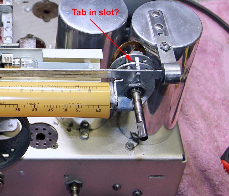
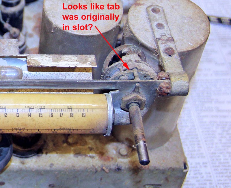
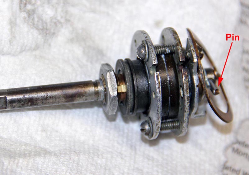
I am having trouble understanding the operation of the vernier control on my GE A-70. I took it apart and cleaned, lubricated it and re-installed it with along with re-stringing the rotating dial. Everything works great except the pointer does not move during fine adjustment. There is only one shaft which I think should automatically switch from fine to coarse when the pin hits the stop on the rear of the control (I attached photos showing the pin and tab).

If I place the tab on nut into the slot on the front of the vernier it prevents the control from switching to coarse and limits the dial travel.  However it appears from my photo of the original set up that the tab is in the slot so I am confused. can anyone shed some light on how this control is supposed to be set up.

Thanks,

Steve D
           
#2

The tab does look like it belongs in the slot. I see a snap ring in the original photo. Was that just holding what appears to be a dust cover or is something possibly missing?
#3

Thanks for you response. I don't see a snap ring and don't remember one when I took it apart.  What appears to be a dust cover I think was actually some dust itself.  The whole vernier was clogged up with dust.

Steve D
#4

I solved this issue by adjusting the three clamping screws to get the proper preload on the ball bearings. I had the screws tightened down too much. The tab does indeed need to be in the slot to prevent rotation of the vernier body and then the screws adjusted for proper operation. This vernier control is intuitive and works very well when adjusted properly.

Steve D


Users browsing this thread: 1 Guest(s)
[-]
Recent Posts
Plug Voltages Needed For A 1943 CRV-20130 Power Supply
That looks a lot like an aircraft connector of some kind, even if it's a U.S.N power supply. I have a book somewhere abo...Arran — 02:56 AM
Plug Voltages Needed For A 1943 CRV-20130 Power Supply
hello david, I have a similar generator in my collection that features a cast iron, single-cylinder Briggs & Stratt...radiorich — 01:00 AM
under chassis parts locator diagram for 1938 Zenith 9s262
Has anyone gone to the trouble of creating an under chassis parts locator image?  Yes, I can identify components by foll...bobloney — 08:57 PM
Plug Voltages Needed For A 1943 CRV-20130 Power Supply
Try looking at this site the book mark is for a old generator that I was given. David    https://radionerds.com/index.ph...David — 08:36 PM
Plug Voltages Needed For A 1943 CRV-20130 Power Supply
Hello Everyone, I am looking for voltage identification for all the pin positions on the socket of a CRV-20130 power su...Tonym4704 — 08:16 PM
Philco P45-6365 Universal Transformer Instruction Manual
Can anyone guide me to where this may be found?GRG — 03:00 PM
54C Complete Teardown/Rebuild
I don't think that I have encountered a 12Z3 before, curious how it uses one of those but includes a #43, which is a 25 ...Arran — 02:17 PM
HiFi (Chifi) tube amp build - but my own design.
It's the other forum. I'm also in DIY, but mostly read there. Honestly, I kinda jumped into this without much thought to...TV MAN — 10:43 AM
Philco 71 Code 125
Hello,  I am in need of a schematic for this radio. Mine has the three separate circular tube shields and a shadow me...dconant — 08:06 AM
Stromberg Carlson 1500 Squeal
And life just keeps getting more complicated.dconant — 07:57 AM

[-]
Who's Online
There are currently no members online.

>