Posts: 641
Threads: 48
Joined: Mar 2017
City: Gap Mills Wv 24941
another interesting thing...
when you get your uglys... find the "INSULATION CHART"
compare that to the information stamped on wiring intended to be exposed to high temps, corrosives, flamable liquids, irregular installations, tightly bundled situations, below freezing, UV breakdown, continuous stress of heating up and cooling down etc...
thats why i mentioned a 10$ junk yard automotive wiring harness with useful color codes exceeds the application of a tube radio.
Best part is 90% of it is flex wiring.
nearly 100% of all the wiring in an automobile will have no information stamped on it,, and if it does,, its because the vendor / supplier just does it.,,not something the auto maker would ask for. The reason is auto makers and others are excempt from NEC compliance yet they are meeting a very stressful application using copper wires.
(This post was last modified: 04-05-2017, 10:47 AM by jcassity.)
Posts: 1,409
Threads: 72
Joined: Oct 2007
City: Linn Creek, MO
18 ga. will be fine, actually a bit of overkill. The NEC tables aren't really applicable to our radios. The NEC tables are based on runs measured in feet where voltage drop can be considerable. We are dealing with wire lengths of a few inches at the most, where the voltage drop is negligible.
Steve
M R Radios C M Tubes
Posts: 16,481
Threads: 573
Joined: Oct 2011
City: Jackson
State, Province, Country: NJ
I usually go by this table:
http://www.powerstream.com/Wire_Size.htm
This is what it has for AWG18: 16A for Chassis wiring and 2.3A for power transmission. For our purpose we should be using the Chassis wiring and not the Power Transmission.
It is good up to 16Amps which is lots more than anyone needs.
People who do not drink, do not smoke, do not eat red meat will one day feel really stupid lying there and dying from nothing.
Posts: 182
Threads: 5
Joined: Feb 2017
City: Cedar Rapids Iowa
Wow - That's a lot of wire info jcassity! Thanks! I actually have the full size version of the NEC book from 1999. I used it to help me pass the test that allows me to do all my own home wiring.
Rich
Posts: 182
Threads: 5
Joined: Feb 2017
City: Cedar Rapids Iowa
Thanks Steve and morzh - I appreciate the input! Now I just need to find a power transformer ;)
Rich
Posts: 182
Threads: 5
Joined: Feb 2017
City: Cedar Rapids Iowa
Yesterday I finally tested the power transformer that was in the 47-1230. It's the one I put in 45 years ago, so not original. It didn't take much input...maybe 10vac...before it was drawing 300ma on the primary, so it looks like it's toast. I still have plenty things that I can work on, but would really like to be able to test it soon, so I need to find a replacement.
Rich
Posts: 736
Threads: 26
Joined: Jun 2013
City: Hayward, California
Hey Rich , I'm pretty sure I have one. I will look this weekend and send it to you. Hopefully its good. Warren
Posts: 107
Threads: 20
Joined: Feb 2015
City: Los Angeles, CA
(03-20-2017, 11:10 AM)criageek Wrote: ...yesterday I removed the pushbutton assembly and it's filthy. What's the best way to clean this up?
I have cleaned several switch and coil assemblies. First I used a small brush and canned air. then I used DeoxIT D5, but used only a very small amount and followed that using foam cleaning (like Q-tips) tips, from the local CVS store to carefully wipe all of the contacts. You already discovered the final step and that is to carefully check all connections for bad solder joints. I have never had any problems using this technique.
Posts: 182
Threads: 5
Joined: Feb 2017
City: Cedar Rapids Iowa
(04-07-2017, 12:15 PM)Warren Wrote: Hey Rich , I'm pretty sure I have one.
That's great! Thanks Warren  When you know for sure shoot me a PM and we'll work out the details.
Rich
Posts: 182
Threads: 5
Joined: Feb 2017
City: Cedar Rapids Iowa
(04-07-2017, 02:44 PM)Tubesforme Wrote: First I used a small brush and canned air. then I used DeoxIT D5, but used only a very small amount and followed that using foam cleaning (like Q-tips) tips, from the local CVS store to carefully wipe all of the contacts.
Thanks Tubesforme!
Rich
Posts: 736
Threads: 26
Joined: Jun 2013
City: Hayward, California
Ok rich, I have the power transformer ready. If you like pm me your address and I will send it to you. Warren
Posts: 182
Threads: 5
Joined: Feb 2017
City: Cedar Rapids Iowa
That's great! Thanks Warren! PM Sent.
Rich
Posts: 736
Threads: 26
Joined: Jun 2013
City: Hayward, California
OK.. the transformer is on its way. I sent it usps priority. You should receive soon.. Good Luck with it. No need to pay me anything for it, just if you can help someone else out here at some time would be nice. Warren
(This post was last modified: 04-10-2017, 03:05 PM by Warren.)
Posts: 182
Threads: 5
Joined: Feb 2017
City: Cedar Rapids Iowa
That's very generous Warren...thank you! I absolutely will help out someone else whenever I can!
Rich
Posts: 182
Threads: 5
Joined: Feb 2017
City: Cedar Rapids Iowa
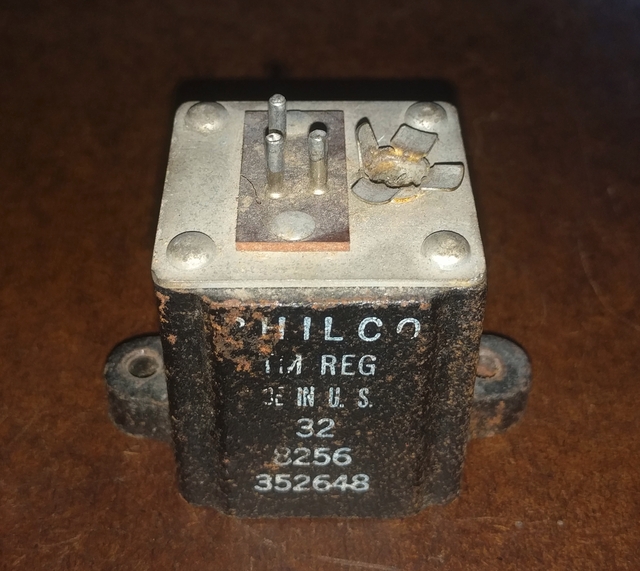
Today's post is about the phono impedance matching transformer. I doubt that these things go bad very often, so this may not be useful to anyone, but just in case, here is the story behind mine. Many years ago the RCA connector on mine was damaged and the center pin pulled out.

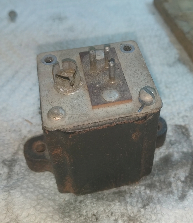
Obviously this is unusable, so I decided I had nothing to lose by trying to repair it. So I took my Dremel with a cutting wheel attachment and was going to just try to grind off the heads of the rivets and then pull the top off. But after cutting a nice groove in the first rivet I decided to try to turn it with a screwdriver, and what do you know...it twisted out! Here I've taken two completely out and one is part way out.

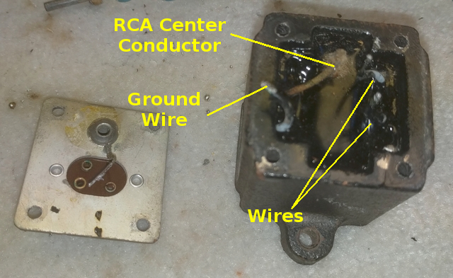
After removing all the rivets I had to heat up each terminal on the connector and suck the solder out of them. The center pin of the RCA connector was already gone but if it had been there it would be removed the same way. Once all the pins were clean I was able to pull the top off.

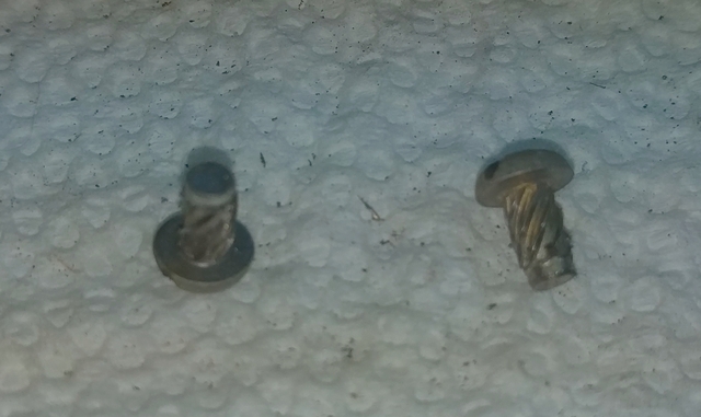
Here's what the rivets look like.

I'm going to have to splice a little wire onto the wire for the center pin of the RCA connector and glue the pin back into the connector. But I think I'm going to be able to salvage it 
Rich
Users browsing this thread: 6 Guest(s)
|
|
Recent Posts
|
|
Zenith H725
|
| Here's what the inside of AM IFT2 looked like, and the other pic shows the discs I made to take place of the mica and ke...EdHolland — 07:40 PM |
|
Zenith H725
|
| IF2 will need replacement caps. The arcing was severe enough that the mica is pitted and holed where the HT flashed over...EdHolland — 04:04 PM |
|
My Philco 37-116 Restore
|
| Measuring from center tap like the tube voltages show. Cap 127 is isolated from ground. Cap 127 shown in upper left of p...dconant — 08:05 AM |
|
My Philco 37-116 Restore
|
| Are you measuring relative to the centertap or the GND?morzh — 11:57 PM |
|
Philco 610B oscillator wiring
|
| Still not clear on the wiring interface between the 6A7 and oscillator. After refering to the available schematics and s...Tubester — 07:18 PM |
|
Refinishing Ideas
|
| My 37-116 code 121 is the best sounding radio i have...a daily driver. Since we are talking about "changes". ...poulsbobill — 07:18 PM |
|
My Philco 37-116 Restore
|
| Hello, I finally got brave enough to take the cans off the Expander Unit. Got the grid cap wires replaced and back toget...dconant — 06:50 PM |
|
Zenith H725
|
| I got into the first AM IF can today, and found its mica was cracked. Amazing that it was still working. This one makes ...EdHolland — 06:10 PM |
|
Philco model #20
|
| AHH HA , I got it and can’t thank you fellows enough , when I changed the capacitors I took the advice and did not unsol...onlyrick — 02:24 PM |
|
Zenith H725
|
| Hello Ed,
yes, I like letting projects run for few days to make sure they don't start acting up .
Sincerely Richardradiorich — 01:03 PM |
|
Who's Online
|
| There are currently no members online. |

|
 
|


![[-] [-]](https://philcoradio.com/phorum/images/bootbb/collapse.png)


