Posts: 1,199
Threads: 49
Joined: Oct 2017
City: Allendale, MI
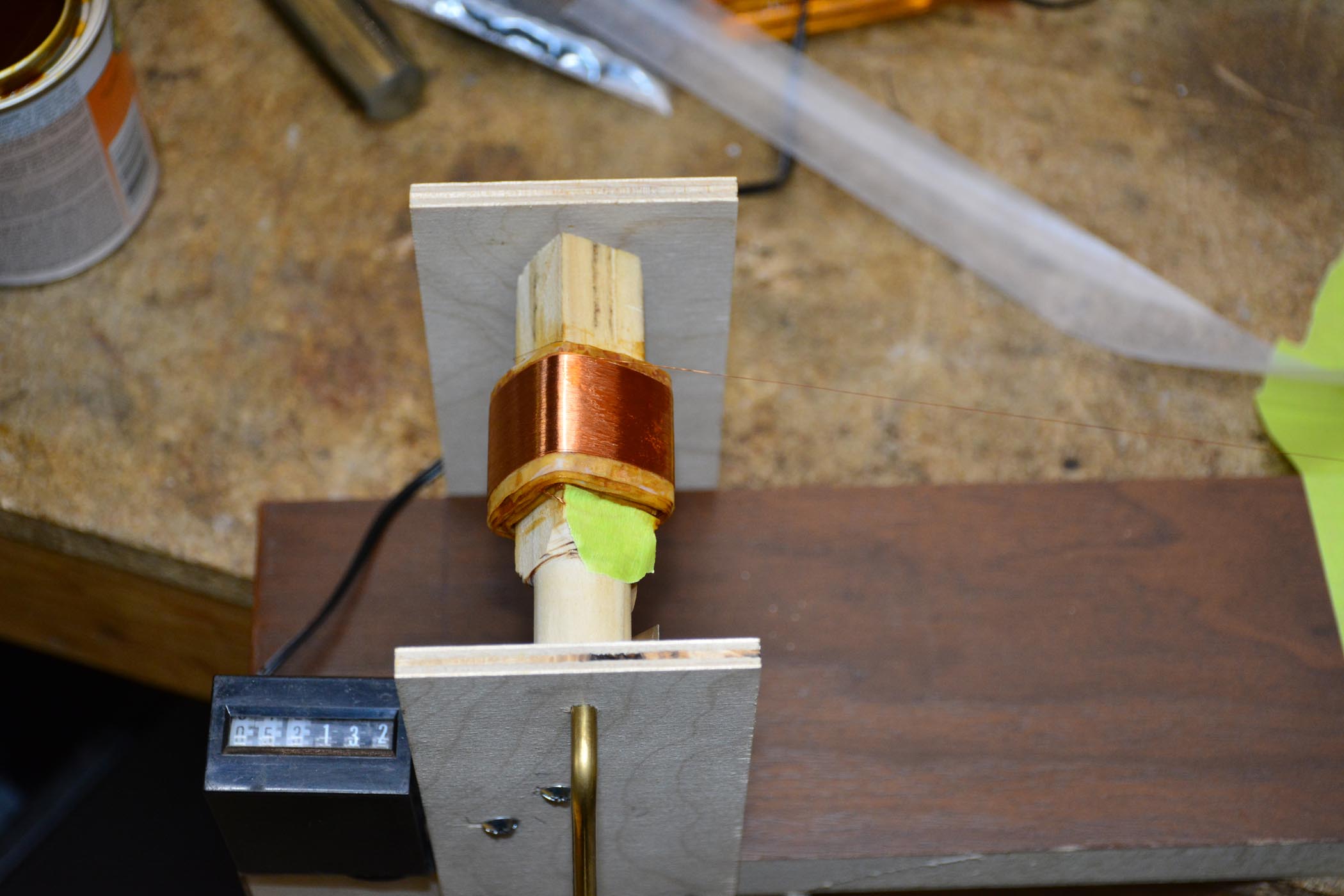
How do you hold it in place? Do you use some wax of some kind? Did you make some sort of coil winding machine that will lay the fine wire down nicely?
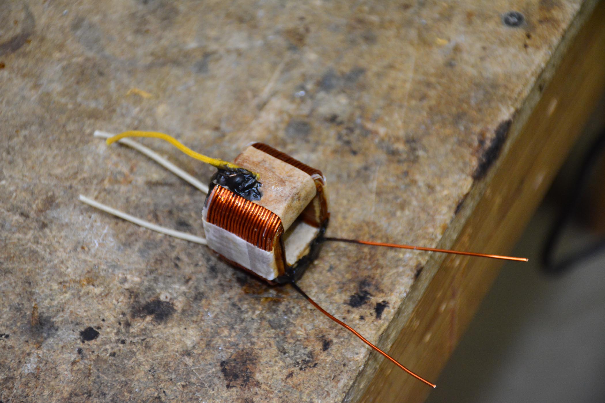
As far as thickness, it was interesting that between layers, there were sometimes 1 layer of paper, other times 2. Don't know if there was a reason or just carelessness on the part of the operator.
Posts: 1,381
Threads: 45
Joined: Nov 2017
City: Menlo Park
State, Province, Country: CA
I held the paper in place with shellac (Bullseye brand from the Hardware store). Something similar was used in manufacture. I cut strips the correct width, trimming them to length after wrapping to achieve an overlap of perhaps 1/2 inch. The windings were painted with shellac, and the paper also "pasted" with it.
Yes, I built a coil winder, Please see my 16X thread here in Electronic Restorations for details of the transformer rewind setup. Looking across the 'net, there are a few ideas for this. I found it took quite a bit of experimentation (learning from scratch). The dissection process of the old windings should also be done with care, notes and pictures - once it is gone, it's gone!
I'm happy to answer any more questions you have.
Ed
I don't hold with furniture that talks.
Posts: 1,199
Threads: 49
Joined: Oct 2017
City: Allendale, MI
Thanks for the info. I didn't take pics but counted every winding of every layer and noted the direction of the wind for the primary and secondary. The number winds, as expected came out very close on either side of the center tap. I'll examine your coil winder and google it for other ideas as well.
Posts: 1,199
Threads: 49
Joined: Oct 2017
City: Allendale, MI
I like your coil winder! Is that a hand crank on the side or do you motorize it? Also, do you find that the fine wire will lay without crossing on its own if you keep a very slight angle on it? I'll be using the 35 gauge wire for the primary as well. Pretty fine stuff.
Posts: 1,381
Threads: 45
Joined: Nov 2017
City: Menlo Park
State, Province, Country: CA
Thanks!
Hand crank, for lack of a motor, but that also enabled good control. The wire will lay without crossing if one is careful to set up the bobbin nice and true. It also helps to pack it a little to bulge the sides - this particularly for the first few layers. Once the stack builds up, it tends to have convex rounded surfaces, and the wire takes up with the angle as you say. I also found it helped to put a new paper under the first layer, to smooth the surface.
I don't hold with furniture that talks.
Posts: 1,199
Threads: 49
Joined: Oct 2017
City: Allendale, MI
I'm going to try it! Since I have a new OT for this radio, it's not the end of the world if I totally botch the job. I just think it would be fun to try. Wire will be here on Thursday, but it's going to take some time to build a winder.
Posts: 1,199
Threads: 49
Joined: Oct 2017
City: Allendale, MI
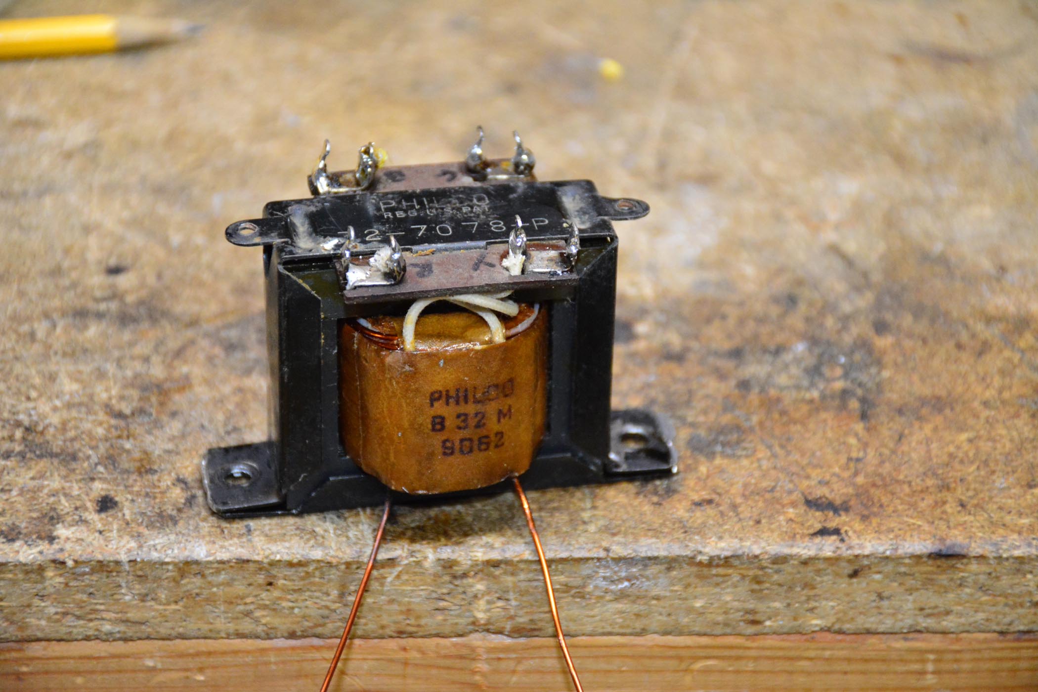
Success! Finished rewinding the output transformer for the 14. I didn't really need to since I had purchased a universal replacement that worked fine. However, My 96 chassis also has a bad output so I thought I would practice on this.


finished product works great. Heck of a lot of work, though. Now I get to do it again for the 96.
(This post was last modified: 12-08-2017, 06:21 PM by rfeenstra.)
Posts: 5,166
Threads: 273
Joined: Nov 2012
City: Wilsonville
State, Province, Country: OR
Posts: 670
Threads: 11
Joined: Sep 2014
City: Bellmawr, NJ
All you Guys,,,,make it look SOOOO,,,easy,,,,,you are killing Me------Nice JOB---CHEERS
Posts: 1,199
Threads: 49
Joined: Oct 2017
City: Allendale, MI
Easy!? that represents probably 3 days work and frustration! As with many things, it's one thing at a time until all added up, it's done. Even though that one transformer cost many $$ in time, there is a sense of satisfaction when it's done and it works. There doesn't seem to be a universal replacement for the 96 output transformer that matches at all closely. So, for it to be correct in the impedance area, I have to rewind it. No Doubt, the universal I have would work and no one would hear the difference. That transformer would look ugly sitting on top of the 96 speaker. I've already disassembled the 96 transformer so I have all the windings counted. Hopefully, with the previous practice, this one won't take as long. An advantage of the 96 transformer is that the secondary was inside the primary so I didn't have to unwind it or rewind it. The harder part is that the primary wire is even finer (37 AWG) than the one I just did (35 AWG). That much harder to keep the wire from crossing in the layers. Hopefully it won't go too badly.
Posts: 4,877
Threads: 54
Joined: Sep 2008
City: Sandwick, BC, CA
I don't think that there were any issues with the quality of Philco output transformers at the time the model 14 was built, that is if the speaker and transformer are the same ages and type as the one that came with the model 14 to begin with. The really crappy output transformers came out in the 1939-42 models, they were usually mounted under the chassis, it's a rare bird to have a model 40-180 style chassis with a good original output transformer, they either have a replacement or an original with an open primary.
Since it was a console chassis apparently it may have had a 10'' "H" type speaker originally, the table version would have had an 8'' "K" type I think. In my opinion the Hammond output transformers, especially the universal ones are overpriced, by far, over what their competitors have on offer, such as Edcor. In a pinch I would have been inclined to search for a NOS replacement, not necessarily a Philco part but a Thordarson or Stancor, or a used one salvaged from a junk chassis or speaker. The impedance isn't really that hard to change on the output side, the secondary windings are towards the outside, undo a few layers of paper and it will be exposed, ready to alter or rewind if necessary.
Regards
Arran
(This post was last modified: 12-10-2017, 03:16 AM by Arran.)
Posts: 13,776
Threads: 580
Joined: Sep 2005
City: Ferdinand
State, Province, Country: Indiana
Wow, good job!  
--
Ron Ramirez
Ferdinand IN
Posts: 1,199
Threads: 49
Joined: Oct 2017
City: Allendale, MI
Thanks Ron.
Arran, I hope you are right about being able to find NOS or replacement by another manufacturer for any future defective output transformers, or PT for that matter, I may run into. This route is a lot of hassle! I'm not too up on the impedance changing thing. I'd have to investigate the math to know how many winds to take off for the secondary. I'll have to google it to see what I can find. For now, this is kind of fun, but it will get old quickly. In past years in the repair of tube type organs, I have run into OT and PT problems and replacements were always available. I always wondered what it would be like to rewind one. Now I know. The customer would never be able to afford that service!
Posts: 1,381
Threads: 45
Joined: Nov 2017
City: Menlo Park
State, Province, Country: CA
Really nice job!
I don't hold with furniture that talks.
Posts: 285
Threads: 18
Joined: Nov 2016
City: Cromwell
State, Province, Country: CT
Very nice job. It's really cool and satisfying when you learn something new or accomplish a hard task like you did. Thanks for sharing and inspiring others.
Tony
“People may not remember how fast you did a job, but they will remember how well you did it”
Users browsing this thread: 1 Guest(s)
|
|
Recent Posts
|
|
Philco 46-480 Electronic Restoration
|
| I was a field engineer for a biomedical company for many years. Many was the time that I was driving home from NYC in t...MrFixr55 — 06:40 AM |
|
Philco 46-480 Electronic Restoration
|
| Don't laugh folks, I have not been above taking a chassis into the bathtub (when Ms. Fixr was out of the house), taping ...MrFixr55 — 06:02 AM |
|
Philco model 40-100
|
| Marion;
By "newer style" carbon resistors do you mean the molded type with coloured bands rather then the BE...Arran — 01:00 AM |
|
Philco 46-480 Electronic Restoration
|
| hello jrblasde ,
your radio sounds great well done !!
I bought like 20 years ago a Philco 610b that someone had painte...radiorich — 11:50 PM |
|
Philco model 40-100
|
| Arran,
I just can't tell if the volume control has been replaced. The control has a brass shaft with one half flat for ...mhamby — 11:08 PM |
|
Philco model 40-100
|
| You may be able to make the part out of wood. The particular vendor has a habit of disassembling radios and selling the...MrFixr55 — 10:09 PM |
|
Philco 46-480 Electronic Restoration
|
| Used to get to Bentonville when I worked for a Walmart vendor....nice and sleepy back then. PaulPaul Philco322 — 09:49 PM |
|
Philco Model 249 made in England
|
| Did Garrard produce stand-alone turntables? The reason I ask is, when I was a kid my grandfather gave me a KLH Model 20 ...jrblasde — 09:37 PM |
|
Philco Model 249 made in England
|
| Neat looking set, definitely Euro- style. I am guessing that this is solidstate due to the vent holes (or lack thereof,...MrFixr55 — 09:32 PM |
|
Philco 46-480 Electronic Restoration
|
| Haha, thank you sir! I’ve been eyeballing a 47-1230 console for sale over north of Bentonville, Arkansas for a while. Pr...jrblasde — 09:18 PM |
|
Who's Online
|
There are currently 645 online users. [Complete List]
» 1 Member(s) | 644 Guest(s)
|
|
|

|
 
|


![[-] [-]](https://philcoradio.com/phorum/images/bootbb/collapse.png)


