12-29-2017, 12:06 AM
Well I proudly tip my hat and offer a heartfelt thanks to Terry for his power supply schematic.  It works like a charm.
The 10 volt winding can be dialed down to 1.5 easily with the potentiometer for the A supply. On the B supply, having only a 6k ohm adjustable resistor I decided to use two 5 watt ceramics I had in house instead. If you have a 10K ohm total adjustable resistor that would be ideal.
I played around with the values (7k & 3K was too low) and found a 4k connected from the positive side of the 47 mfd electrolytic to B + and a 5k connected between the B+ and B - connections gave me 94 volts which was right on with what I was getting with ten 9 volt batteries strung together. Of course that was without a load. Once installed and the radio is playing, it drops down to 76 volts. I should have taken that into account and went with a higher value resistor between the B + & B - and a smaller value from the lytics to B + to have over 100 volts without a load. Then it would've been perfect. But, it plays great as it is, so I'm not complaining.
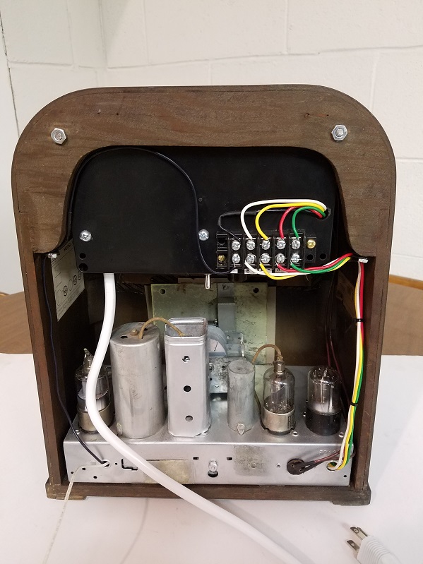
It took a lot of finagling to get everything to fit inside the enclosure box I got from Amazon:
https://www.amazon.com/gp/product/B06XSQ...UTF8&psc=1
But I got it all in, plus added a toggle off/on switch and an indicator lamp.
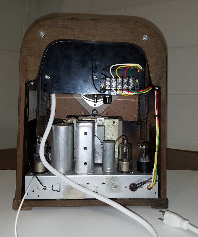
Best of all, it fits nicely inside the cabinet!!

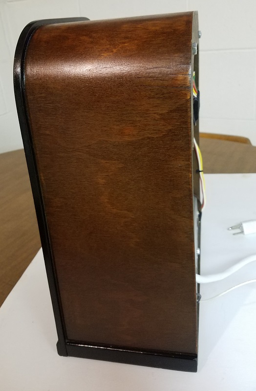
It's even flush with the back of the cabinet too:

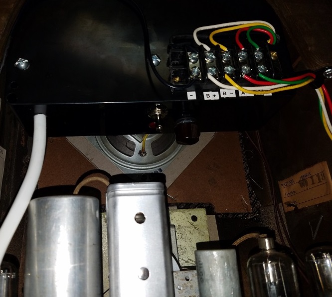
Here is the bottom side of the box showing the toggle on/off switch, light and potentiometer to adjust the A voltage:

You need to use a 3 prong plug and connect the ground wire from the radio chassis to the ground wire in the cord to eliminate buzz (unfortunately I only had a white colored cord on hand but that's a minor detail).
I'm very pleased with with this power supply and would recommend it to anyone who wants to convert a 90 volt "B" / 1.5 volt "A" battery powered farm radio to run on AC.
Thanks again, Terry!

The 10 volt winding can be dialed down to 1.5 easily with the potentiometer for the A supply. On the B supply, having only a 6k ohm adjustable resistor I decided to use two 5 watt ceramics I had in house instead. If you have a 10K ohm total adjustable resistor that would be ideal.
I played around with the values (7k & 3K was too low) and found a 4k connected from the positive side of the 47 mfd electrolytic to B + and a 5k connected between the B+ and B - connections gave me 94 volts which was right on with what I was getting with ten 9 volt batteries strung together. Of course that was without a load. Once installed and the radio is playing, it drops down to 76 volts. I should have taken that into account and went with a higher value resistor between the B + & B - and a smaller value from the lytics to B + to have over 100 volts without a load. Then it would've been perfect. But, it plays great as it is, so I'm not complaining.
It took a lot of finagling to get everything to fit inside the enclosure box I got from Amazon:
https://www.amazon.com/gp/product/B06XSQ...UTF8&psc=1
But I got it all in, plus added a toggle off/on switch and an indicator lamp.
Best of all, it fits nicely inside the cabinet!!
It's even flush with the back of the cabinet too:
Here is the bottom side of the box showing the toggle on/off switch, light and potentiometer to adjust the A voltage:
You need to use a 3 prong plug and connect the ground wire from the radio chassis to the ground wire in the cord to eliminate buzz (unfortunately I only had a white colored cord on hand but that's a minor detail).
I'm very pleased with with this power supply and would recommend it to anyone who wants to convert a 90 volt "B" / 1.5 volt "A" battery powered farm radio to run on AC.
Thanks again, Terry!
Greg V.
West Bend, WI
Member WARCI.org


![[-] [-]](https://philcoradio.com/phorum/images/bootbb/collapse.png)


