Restoring a 46-1226 Code 125
Posts: 348
Threads: 48
Joined: Oct 2013
City: Tioga, Texas, USA
As it turned out, when I tried using the changer the way I had mounted it was too high in the cabinet and raising the record support arm when loading records was all but impossible. The solution is to remove the bottom part of the plastic base of the changer and use a piece of 1/4 inch plywood to attach it to the original Philco rose colored base frame. That will allow use of the changer in a much more comfortable and accessible manner. It will have to wait a few days as the weather is rather raw and cold here now. I have to do that work in the barn and there is no heat there.
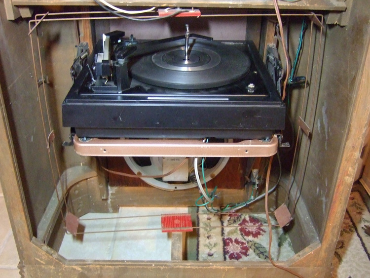
In the meantime I did take a picture of the changer in place when the unit was too tall. Here is that picture:

You can see the lower indented part of the base in the picture. That part can be removed by taking out some 1/4" hex head screws and that is where the plywood piece will go. That lowers the entire unit about 1.5 to 2 inches which is enough to make the unit much more accessible.
Joe
Posts: 348
Threads: 48
Joined: Oct 2013
City: Tioga, Texas, USA
I changed my mind about getting a tube type preamp and decided to go with a transistorized one. I found a Bozak unit for about $15 with free shipping. I can wire it to come on when power is applied to the changer from the AC switch in the radio chassis. Since it will be instant on, there will be no delay when switching to phonograph function with the radio function knob. It will also be physically smaller and easier to find a spot for in the cabinet.
This will allow me to finish the electronic related issues with the unit faster and then I can move on to repairs to the cabinet. The cabinet has some missing pieces of veneer at the rear of one side and one piece on the front of the phonograph compartment. I can get replacement veneer at Rockler and get the cabinet looking better. It will not be exactly like it was when new, but I am not a cabinet maker and do not have all the tools which a full cabinet restoration would require. The front will be very presentable after the phono compartment is repaired and if the cabinet is near other furniture no one is really going to notice the spliced pieces of veneer on the one side.
Joe
Posts: 348
Threads: 48
Joined: Oct 2013
City: Tioga, Texas, USA
As things turned out, I can not use the upper portion of the BSR-310 base as it is wider than the bottom half and it rides up as the phonograph door is closed on the top edge of the front pivoting steel brackets. Either the brackets would have to be modified or the sides of the upper half base would have to be modified to prevent the brackets pushing up the front of the changer base when the door is closed.
I wound up using a piece of left-over 1/2" birch plywood from another project and made a new wooden base for the changer. I used the old plastic base as a template for determining where to drill 1/2" holes for the changer hold-down screws and the internal cut-out for the changer mechanical items underneath. I drilled the 1/2" holes with the old changer base taped to the plywood so things would not shift. Once those holes were done, I moved on to drilling some entry holes for my saber saw blace and made the interior cut. I finished the internal cut shaping and sanding using a cylindrical grinding bit in the chuck of my Dremel tool. Some final sanding to get rid of any remaining burrs and roughness resulted in a decent looking base.
I found that a can of MinWax Special Walnut stain looked closest to the OEM stain used on the inside of the phonograph compartment and used that to stain the new wooden changer base. It is now curing in the barn. After a day or so I will apply some polyurethane varnish to the base and mout it using some screws and fender washers. The front of the wooden change base will also receive shims made of flat washers to equal the height of the rear OEM changer mounting brackets and screw heads.
The Bozak preamp I ordered has not arrived yet. It is coming USPS and the tracking number does not show up in their system yet - not sure why not. The Bozak preamp is supposed to work with loads from 100 to 100K ohm impedance. I am thinking of changing the 150K load resistor originally used with the phonograph function to a 47K ohm. Alternatively a test could be made with a variable resistor to find the best overall phonograph volume level compared to the radio functions.
I will take some more pictures when I install the wooden base.
Joe
Posts: 348
Threads: 48
Joined: Oct 2013
City: Tioga, Texas, USA
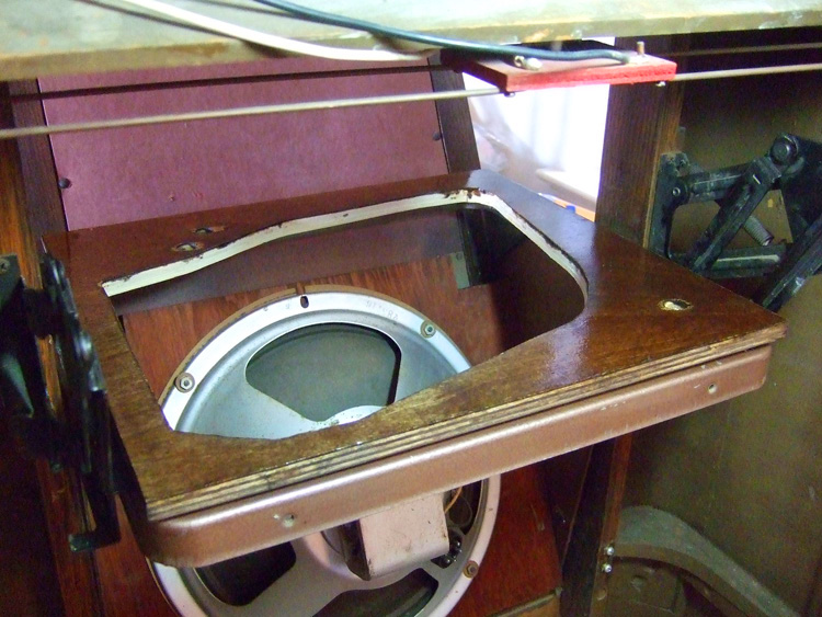
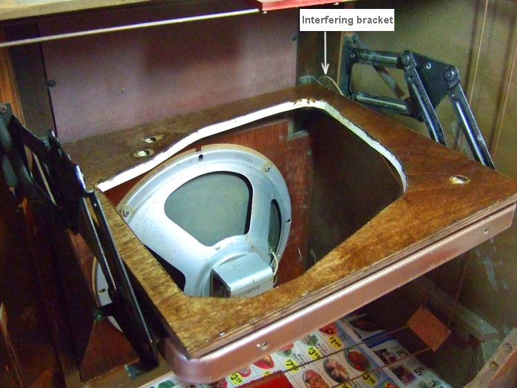
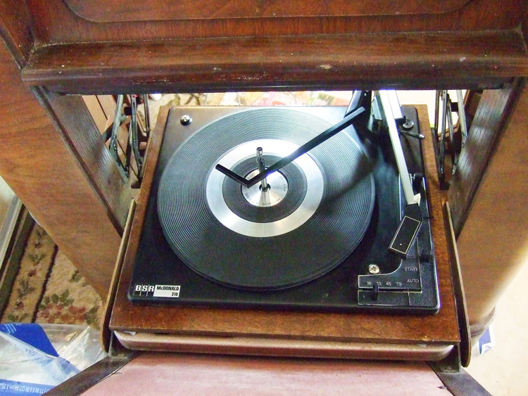
I did get the wooden changer base made, stained and varnished. The installation to the OEM changer base was done this morning. By using the wooden base arrangement, the changer vertical position in the cabinet is further lowered for better access to the changer for loading and removing records. This will be an additional advantage to the user. Here are some pictures:


In this picture you can see that with the changer door closed the bracket pointed to rises and is the bracket that interferes with the BSR upper portion of its base when I was trying to use the BSR base. That would have been less trouble to do, but unfortunately it did not work out because of the position of this part of the moving brackets on each side at the front of the OEM Philco changer base. Using a wooden base cut to be less than the distance between the two brackets allows the wooden base and changer when mounted to move freely with no interference.

This picture is taken from the front of the radio cabinet showing the position of the changer when the door is opened for access for adding or removing records.
I did change the 150K ohm load resistor in the radio chassis to a 47K ohm resistor to provide a better load for the preamp when records are being played.
Joe
Posts: 640
Threads: 48
Joined: Mar 2017
City: Gap Mills Wv 24941
i lost track of something or maybe missed a post,, but,, you are missing the original turn table?
i dont ever plan to install mine back in.
Posts: 348
Threads: 48
Joined: Oct 2013
City: Tioga, Texas, USA
JC;
The original 79rpm changer came with the unit. I removed it and placed it in a storage box and it will be returned to the owners when the radio-phonograph is returned to them. They had no desire to keep the old changer and wanted a modern changer that would play all speeds and sizes of records. The BSR provides that capability for them. The BSR-310 I chose came with a Shure magnetic stereo cartridge, so they will be able to play stereo records without worrying about damaging the records.
I have been working on the changer installation today. I have mounted the Bozak preamp to the rear of the old changer base and made a Y-audio cable to bring the left and right channel outputs together for a monophonic signal. I have been re-organizing the associated cables and securing them so that they do not interfere with moving parts such as the door moving hinges and the rotatable AM Loop antenna. I made a trip back to a hardware store today to get parts for adding an AC outlet to the right of the radio chassis which will fasten to the wooden horizontal rib that supports the rear of the radio chassis. The preamp and the changer will plug into the receptacle so that for service the changer can be removed separately without having to remove the radio chassis. The Phonograph function AC cord will connect to the receptacle and when the radio is switched to Phonograph operation it will turn on the AC to the changer motor circuit and the solid state preamp at the same time.
I will take some pictures when done.
Joe
Posts: 348
Threads: 48
Joined: Oct 2013
City: Tioga, Texas, USA
After doing a check-out of the unit I find that both the radio and the phonograph functions exhibit a severe distortion when the volume is turned up beyond a certain point. I need to check the volume control for a possible cracked carbon trace - perhaps open above a certain point of rotation. Otherwise it may require connecting an oscilloscope to find where the distortion begins. I first thought some time ago that it was due to weak audio output tubes, but replacements from a known good amplifier proved that not to be the case.
More to come on the distortion investigation.
Joe
(This post was last modified: 01-11-2018, 01:03 PM by Joeztech.
Edit Reason: wrong word
)
Posts: 640
Threads: 48
Joined: Mar 2017
City: Gap Mills Wv 24941
i had carbon trace on two of my loctals,, one was the 7af7 and the other was another which was cherry to get to and repair.
the easy one to get to was the first i found, so i didnt have spare loctal sockets at that time.
I took the loctal apart, laid the insulator disc on 2000 grit sand paper and sanded down past the carbon ditch it made.
I taped off and sprayed the exterior of each pin with spray electrical insulator, (comes out redish in color). put it all back together and that got rid of my reistance to ground on the one pin that was messing me up.
I found the carbon trace on the bottom side of the disc insulator by the way, it was not on the top.,,, so the only way to see is to take it apart.
lucky for me i was told to tone each pin to chassis to see if i had this possible fault and sure enough one pin was reading a few hundred ohms to ground.
(This post was last modified: 01-11-2018, 01:04 PM by jcassity.)
Posts: 348
Threads: 48
Joined: Oct 2013
City: Tioga, Texas, USA
This morning I took the chassis out of the cabinet again to look at the volume control and the distortion issue at high volume. I was distrustful of the audio coax that went to the high end of the volume control, so I changed it. It appears that short piece of coax has the shield grounded only at one end and is only a few inches long. I cleaned up some of the solder connections to the volume control. I had already cleaned the controls with Deoxit control cleaner. There is a tap on the volume element some amount above ground which goes to the tone control through a capacitor. I decided to look at the resistance measurements with my ohm meter to see what I could determine about the volume control as it is rotated. The strange thing is that with one end of the meter grounded to the chassis and the other connected to the center variable lug of the control the resistance goes to near ground when the shaft is rotated fully counter-clockwise and rises as it is advanced clockwise, then goes down for a space, then rises again to a very high value and then goes to close to ground again at maximum rotation. That is not normal. The next step will be to disconnect leads and remove the control and open it up to see if there is some debris inside. One other thing I have seen with a few controls over the years is that some have a bit too much ability to rotate clockwise until the moving finger on the trace passes the end of the carbon trace enough to connect across the gap between the high end and the low end of the carbon trace. I hope that is not what is happening.
Since there is not a resistance path to ground through the tone control (or should not be according to the schematic) I do not see any apparent reason for the dip in the resistance to ground as the control is rotated clockwise. I will report on this later.
Joe
(This post was last modified: 01-12-2018, 07:50 PM by Joeztech.
Edit Reason: misspelled word
)
Posts: 348
Threads: 48
Joined: Oct 2013
City: Tioga, Texas, USA
OK, I found the problem - it was a solder splash, probably my own fault. I removed the solder splash then looked at distortion as I turned the volume up. With the original 6K6 tubes in the output stage there was inadequate volume at maximum and replacing the 6K6 tubes with 6V6GT tubes cured the low volume. It now has adequate volume range. I also found that the B+ filtering was inadequate and added a 40uF @ 450VDC to the B+ source that has the orange wire as a distribution bus. That removed the residual hum and it sounds quite nice now.
Now I get to re-install the chassis in the cabinet once again and see how it sounds.
Joe
Posts: 13,776
Threads: 580
Joined: Sep 2005
City: Ferdinand
State, Province, Country: Indiana
You're doing great, Joe... 
--
Ron Ramirez
Ferdinand IN
Posts: 348
Threads: 48
Joined: Oct 2013
City: Tioga, Texas, USA
Ron;
Thanks! I am convinced that these models are capable of some decent sound and I kept noticing that the response to the volume and tone controls kept changing as the radio warmed up. I finally decided to replace many of the resistors in the Phase Inverter and 1st. Audio stages. They were all OEM parts and were 20% tolerance parts. I began checking their values and found many were more than 20% off value, so I changed them. The radio is now playing and sounds better (less distortion even with elevated volume). I will leave it on for hours now and see if anything else develops. So far it is noticeably better than it was.
The BSR changer appears to need the idler/drive wheel surface sanded lightly to remove glaze. It does not want to go completely through a change cycle when cold without some assistance. The change cycle gear has already been removed, cleaned and relubricated. That made a significant difference in the ability of the changer to work properly. The motor shaft spins freely, so that is not the source of the problem. The turntable has been cleaned and relubricated too, so it is eliminated as a problem source too.
More later.
Joe
Posts: 348
Threads: 48
Joined: Oct 2013
City: Tioga, Texas, USA
Jcassity;
I notice that the warm-up time of this radio is extremely long - about 2 minutes (no audio until then, weak at first and growing stronger until volume is full). The audio sounds quite good when it is fully warmed up, but two minutes is too long. The schematic says the grid bias on the output tubes is supposed to be -11VDC. What do you measure on your radio? I did note that the 1st IF tube seems noticeably cooler than the second one. I may have to revisit cleaning the tube sockets. I have some of the dental flossing brushes that I can use to get into the socket contacts along with the Deoxit application. I need to measure the AGC voltage and see if that is changing slowly on warm-up. Right now I have 6V6GT tubes installed in the output sockets. I might try the original 6K6 tubes and see how they warm up by comparison.
The 6V6GT tubes produce more volume than the 6K6 tubes did, so they may not be the issue.
Joe
Posts: 348
Threads: 48
Joined: Oct 2013
City: Tioga, Texas, USA
In the course of checking some voltages in the radio chassis, I discovered that the AGC voltage goes to about +12VDC which is not necessarily what I was expecting. The grid bias at the output tubes signal grids are at -19.9VDC. That does not change during warm-up but after about two minutes the audio comes up. I also discovered by measuring the voltages on the cathode resistors of the IF tubes that the 1st IF appears to rise to beyond 8VDC and goes all the way to +131 volts after a while! The 68 ohm cathode resistor measured about 72 ohms and since the voltage there was so high, I decided to replace it with another 68 ohm resistor. That resistor performed the same way and also wound up measuring about 70 ohms or more after cycling one time with the +131volts showing up on the cathode circuit. The tube checks OK on the tube tester and has good emission. I suspect the tube socket is defective and has a B+ internal bridge in it.
So it appears I need to order some Loctal sockets. These will not be easy to change. I am thinking about changing this one to a conventional Octal socket and replacing the 1st IF tube with a suitable Octal base tube. I never saw any real advantage to Loctal tubes and sockets.
Joe
Posts: 13,776
Threads: 580
Joined: Sep 2005
City: Ferdinand
State, Province, Country: Indiana
I think you have a very good idea there in replacing loctal with octal. Loctal tubes were, in my opinion, one of the worst ideas Philco ever came up with. It ranks right down there with the RF units of 1937-38. 
OK, yes, I know Sylvania developed the loctal for auto radios and airplane use. It was still a bad idea...especially in home radios.
--
Ron Ramirez
Ferdinand IN
Users browsing this thread: 1 Guest(s)
|
|
Recent Posts
|
|
Philco 89 Code 123 Osc Coil
|
| Hello,
I thought I would post my findings on my bad oscillator tickler coil. There were 27 turns on the outer coil b...dconant — 12:38 PM |
|
Philco Model 16 wiring question
|
| Thanks Morzh. So it appears I did wire it incorrectly and I have to switch the wires between pins 2 and 4.bobclausen — 09:24 AM |
|
Philco 46-1209 strange behavior
|
| No, it's not a problem, just during certain condition it could show up.
Yes, an internal tube short could do that too.
...morzh — 09:13 AM |
|
HiFi (Chifi) tube amp build - but my own design.
|
| You sound guys are never satisfied. :crazy: :clap:RodB — 09:10 AM |
|
HiFi (Chifi) tube amp build - but my own design.
|
| I got some new ceramic octal tube sockets installed and also tried some different coupling caps.
The results:
The go...TV MAN — 08:42 AM |
|
Philco 46-1209 strange behavior
|
| I pulled the tube out and it's shorted from pin 1 to pin 2. I suppose that's the problem...sq65 — 08:12 AM |
|
1949 Motorola 5A9M
|
| bob
Nice work on battery . If you don't. Have terminals i have a few spares
Samsam — 02:12 AM |
|
1949 Motorola 5A9M
|
| hello mr Fixr,
for sure !!
I have some radios that I need to make some batteries for too.
Sincerely richardradiorich — 12:33 AM |
|
1949 Motorola 5A9M
|
| Dittos, sweet b on the battery. Love the "9 Lives" logo, remembered from my childhood. Other neat ones are t...MrFixr55 — 11:24 PM |
|
Philco 46-1209 strange behavior
|
| Hi Morzh,
Dunno if the AC EMI caps are an issue. I never liked the concept but never had an issue with these causin...MrFixr55 — 11:21 PM |
|
Who's Online
|
There are currently 1017 online users. [Complete List]
» 1 Member(s) | 1016 Guest(s)
|
|
|

|
 
|


![[-] [-]](https://philcoradio.com/phorum/images/bootbb/collapse.png)


