Parmak rebuild (Parker McCrory)
Posts: 1,204
Threads: 84
Joined: Jan 2014
City: Annapolis, IL
State, Province, Country: USA
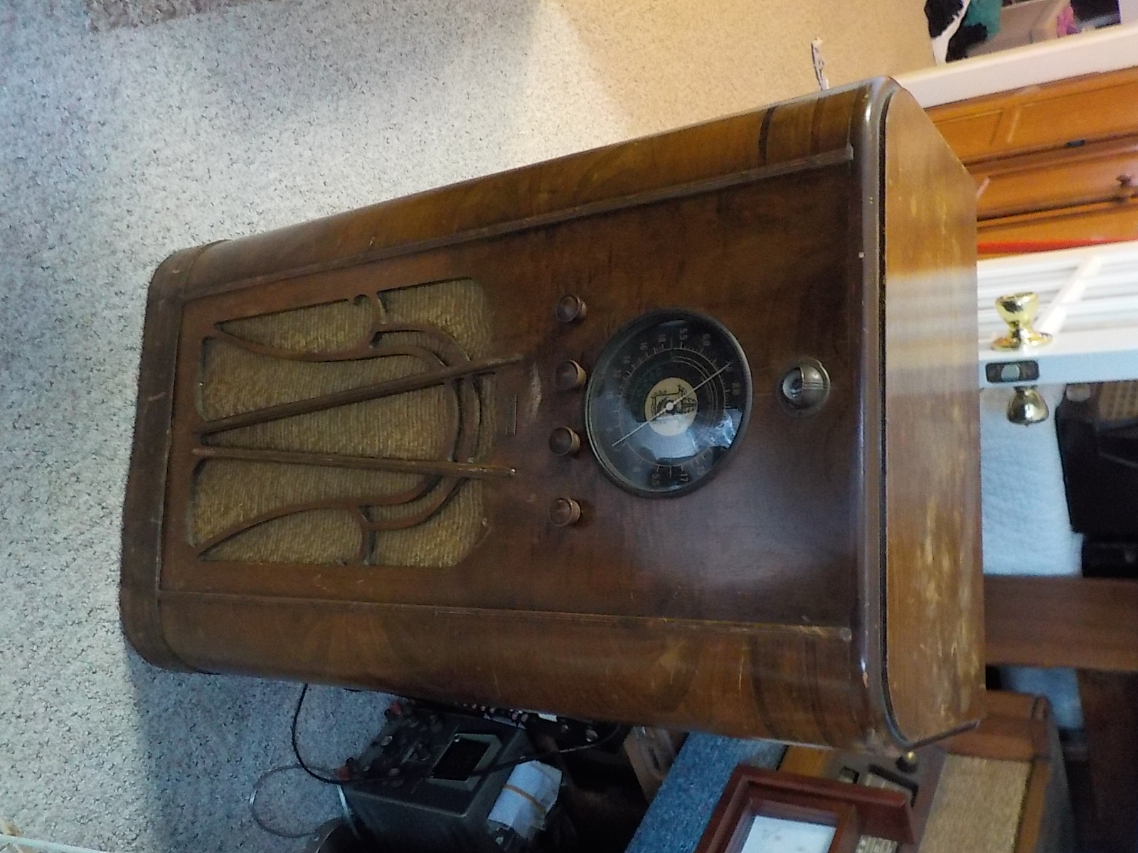
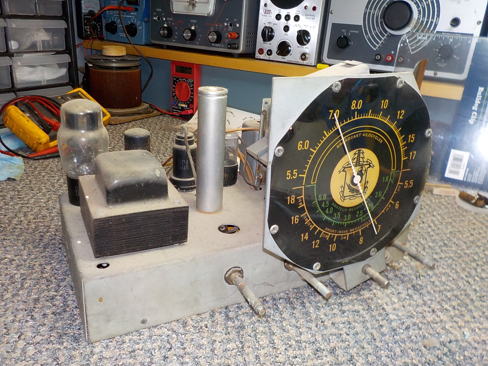
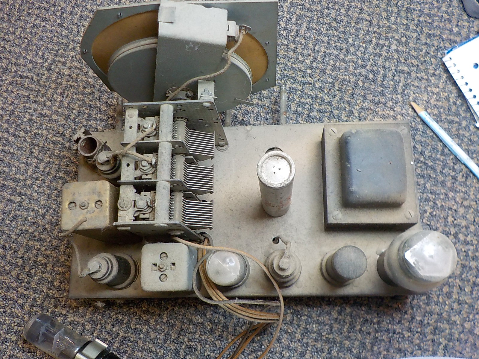
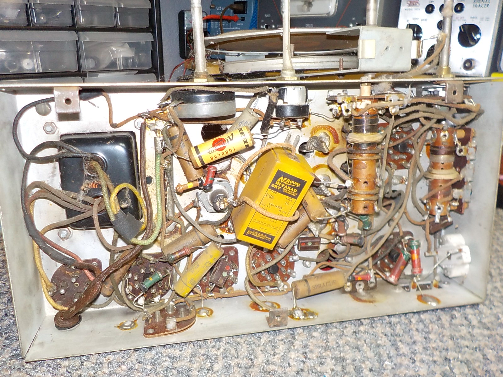
I often take a break from the internet in January (some may have observed this in the past), but I have spent some time in the radio room. A few years ago I scored a Parker McCrory (Parmak) console from a local antique store. I liked the looks of it due to the large dial and eye tube. We had it in out living room and I got tired of people asking 'Does it work?" So, I flopped it up on the bench and started some checks. The initial tests revealed the power trans and speaker field may be ok. Open primary on the output transformer. Next I tested the tubes. I found a weak IF tube (6K7) and a dead 6F5 and 6E5. All others tested good, even the 80! I started the recap. It seems to have gone well overall. You can see that I decided to use discrete e-cap instead of messing with restuffing. I connected to the output transformer on the signal tracer for testing purposes.
Upon a slow power up, I was amazed to find it was picking up stations! It wasn't real strong, but showed me that everything was working. I started doing some fine tuning (not the alignment) and here was what I have found: Upon powering up it would sometimes make shrieking and popping noises. I noted that it had an (undersized) universal output transformer. It had been replaced at some point. It went dead on the 3rd power up, some some quick observations noted the tuning eye tube was showing it was tuning in stations. Ok, onward. A finger test on the 6F5 grid cap produced nothing. I poke with a meter probe on the 6F6 grid produced a hum. The 6F5 died, so I rummaged around and found a fairly decent replacement. This brought the radio back to life. I suspect this is what killed the output transformer, and probably the one prior. It plays fairly well, but is weak on volume. Tuning seems sensitive. This may be due to the mismatched output test transformer.
Now, I havent been able to find any schematic in riders for this, so I dont know if this was an odd one run make or was bought out by another company. The model number is 105212 as far as I can tell. I am having to use my instincts on this one, but any help would be appreciated as far as a diagram, experience, or history.
The 6F6G output tube appears to need a transformer with a 7000 ohm or so plate load according to the RCA tube manual. Judging from the size of the speaker (about 12"), I am guessing the trans to need to be about a 5w. It has around 200v on the plate. I have no idea what the impedence of the speaker is. It does work, but again, very weak.
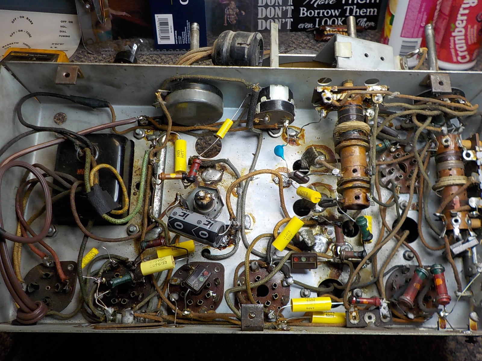
Here are a few pictures of things before I started the recap:
More to come...
If I could find the place called "Somewhere", I could find "Anything" 
Tim
Jesus cried out and said, "Whoever believes in me , believes not in me but in him who sent me" John 12:44
Posts: 1,204
Threads: 84
Joined: Jan 2014
City: Annapolis, IL
State, Province, Country: USA
More observations and pictures: It appears that this has had quite a bit of repair work done in the past, even up to a full recap. Most of the caps I removed were Spragues. I also suspect the tuning eye tube may have been added, since it uses a 6E5, rather than the older 6U5. Could have been modded to accept the newer tube, but I can't tell for sure. It does look like it was fairly decent repair work previously.
I do have a few issues and questions. It only had one electrolytic cap coming off the cathode of the 80. No others. The neg from the original can is not grounded and has (I believe) a negative voltage to chassis ground. The old replacement had the negative going to a tap on the bias candohm resistor instead of across the original. I connected the new cap across the original (of course, removing the old cap from the circuit). It had a little hum, so I tried it the way the replacement was in. It made the hum a lot worse, so I returned it to the original position. I suspect the hum may be due to not using the hum bucking coil on the original speaker.
I also noted the power transformer had been replaced. The eye tube brightness will flicker when the volume is turned up, to the tune of whatever is being played. When it is turned down, it is normal. The B+ jumps around when the volume is up. May be the wrong output trans? Or, the wrong power trans? I tried adding another electrolytic in parallel. No change. I am using a 10mf cap (original was 12, and the old replacement was 16).
So, I am hunting an output trans. Found a maybe from Hammond. Any suggestions or ideas from what I have shared so far?
Below is a close up of the power supply area. You can see the stub of the replacement e-cap wire from a previous repair on the candohm. 2nd lug from the top. I left that to remember where it had been in case I needed to move the new cap neg to that point.
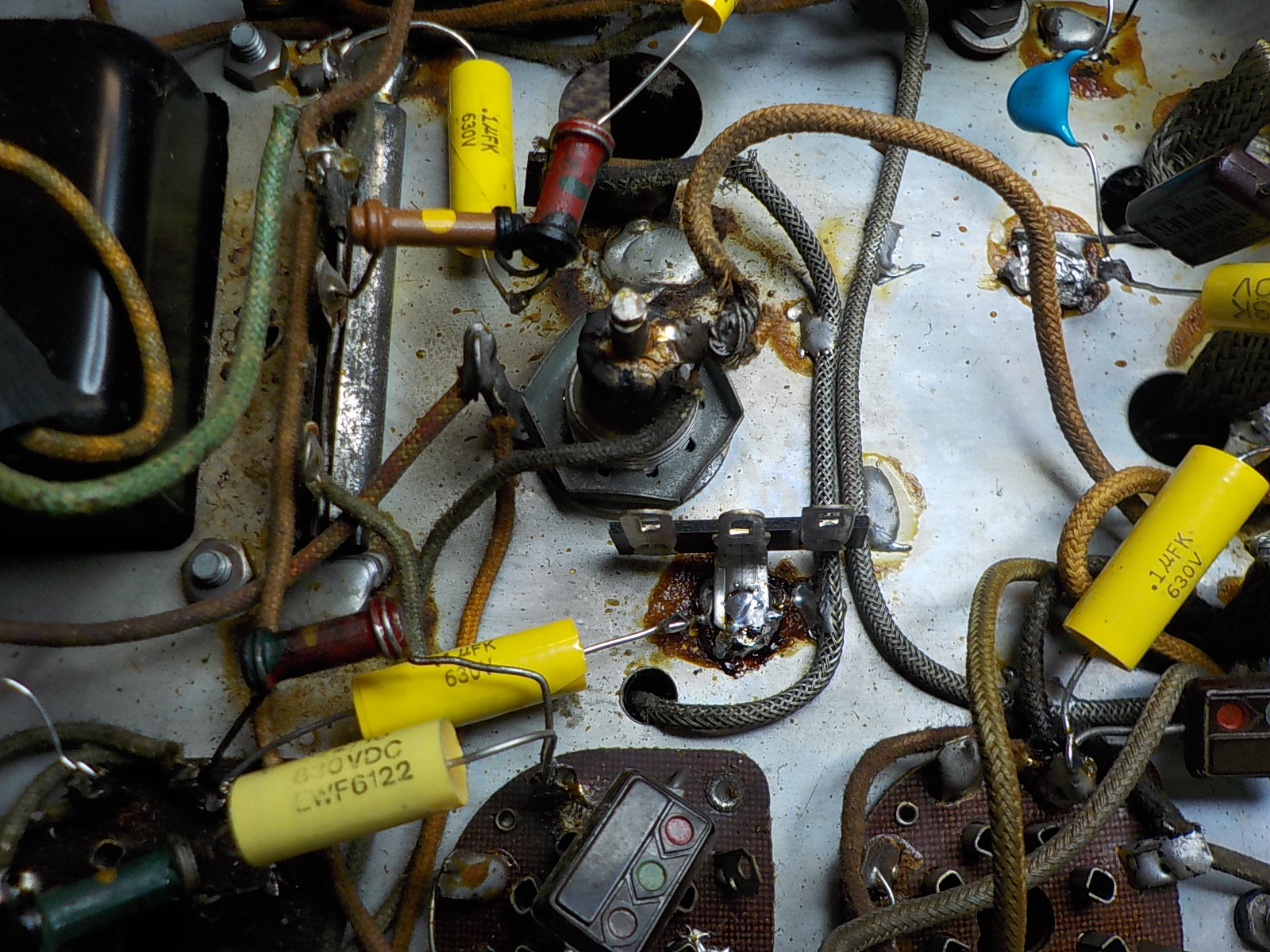
Overall recap
If I could find the place called "Somewhere", I could find "Anything" 
Tim
Jesus cried out and said, "Whoever believes in me , believes not in me but in him who sent me" John 12:44
(This post was last modified: 01-29-2018, 04:57 PM by TV MAN.)
Posts: 1,204
Threads: 84
Joined: Jan 2014
City: Annapolis, IL
State, Province, Country: USA
I found a couple maybes from AES. Any idea how to tell the speaker impedence?
https://www.tubesandmore.com/products/tr...nder-5w-7k
https://www.tubesandmore.com/products/tr...unior-15-w
I am certainly open to ideas at this point. Cost is a factor as is performance.
If I could find the place called "Somewhere", I could find "Anything" 
Tim
Jesus cried out and said, "Whoever believes in me , believes not in me but in him who sent me" John 12:44
Posts: 4,870
Threads: 54
Joined: Sep 2008
City: Sandwick, BC, CA
You have it backwards, the 6E5 was the original Magic Eye tube introduced by RCA in 1935, the 6U5/6G5 came later, the 6E5 is more sensitive to changes in grid voltage so that was why they came out with the later types. That doesn't mean that someone didn't add the eye tube, I've seen them added even on early 30s sets sometimes. As for the filter capacitors it may have been that the positives were connected together and the speaker field coil was connected in the negative leg of the power supply, such as between the transformer center tap, and the chassis, with some bias resistors in series with it. I doubt whether you will need a replacement power transformer, most of the time they can be made to work unless the transformers are completely wrong like the transformer is too small to handle the load, or is putting out 2.5 volts for the filaments when you need 6.3. The old output transformer can be replaced with a generic single ended unit, you don't need a universal one, one of at least 5 watts should be sufficient. Like this one here: https://www.tubesandmore.com/products/tr...ngle-ended
In terms of faults I would check those old dogbone resistors, that may account for the weak performance, as would a wiring error from not having a schematic to go by. I will see if I can find a schematic for this thing, I would pin the age at about 1936-37 or so, that model number sounds like a serial number so I will search by chassis layout and tube lineup,
Regards
Arran
(This post was last modified: 01-30-2018, 06:26 AM by Arran.)
Posts: 1,204
Threads: 84
Joined: Jan 2014
City: Annapolis, IL
State, Province, Country: USA
Thanks for the correction on the eye tubes. I did think it was the other way around. I do note the field coil was on the low side of the B supply and didn't have much voltage (maybe even a negative voltage to chassis ground) on it and does connect to that candohm and center tap. Thanks for the lead on the output trans. The power trans seems fairly robust. I will try to check those dog-bones. This is where my wife's eyes will come in handy. She sees color where I see in black and white lol! I did some internet searching but came up empty on this one for a schematic. It uses a 6A7, 6K7, 6F5, 6H6, 6F6 6E5 and 80. AM + 2 short wave bands.
If I could find the place called "Somewhere", I could find "Anything" 
Tim
Jesus cried out and said, "Whoever believes in me , believes not in me but in him who sent me" John 12:44
Posts: 7,300
Threads: 268
Joined: Dec 2009
City: Roslyn Pa
Would have a look at the 150K resistor between the 6K5 and 6F6. Common for those to go high rendering low voltage the the plate of the 6K5.
GL
When my pals were reading comic books
I was down in the basement in my dad's
workshop. Perusing his Sam's Photofoacts
Vol 1-50 admiring the old set and trying to
figure out what all those squiggly meant.
Circa 1966
Now I think I've got!
Terry
Posts: 3,152
Threads: 56
Joined: Apr 2011
City: Lexington, KY
Tim, have you tried the Free Radio Database yet? It doesn't recognize Parmak or Parker, nor does entering it as a 7 tube set. So guessing that maybe the 6E5 was a later addition I entered it as a 6 tube set and got some hits..... maybe one of them will be close???
http://grillecloth.com/sylvania/tubelist...ubmit&db=5
John KK4ZLF
Lexington, KY
"illegitimis non carborundum"
Posts: 4,870
Threads: 54
Joined: Sep 2008
City: Sandwick, BC, CA
I had a look through the Parker-McCrory schematics listed on Nostalgia Air, and the vast majority seem to be battery sets, either full blown ones with "A" and "B" batteries, or vibrator supply types, there were a few AC sets but those seemed to be newer and with pushbuttons. I'm wondering if Parker-McCrory was the manufacturer, the chassis construction and dial design kind of remind me a Musicaire radio I have built by Sentinel? I'm also wondering if this may have originally been a 6 volt operated vibrator set at one time, except that I'm sure there would be more evidence of that such as marks where the tin box containing it all was located. If it was converted it was done a long time ago, the power cord is made out of natural rubber. I can see what you mean about the eye tube, the way that they routed that cable looks amateurish, it's unlikely that a factory would have routed the wires through the same hole as the grounding strap for the tuning condenser, all the other eye tube equipped sets I've seen had the cable routed through a 1/2'' hole usually lined with a brass grommet.
Regards
Arran
Posts: 4,870
Threads: 54
Joined: Sep 2008
City: Sandwick, BC, CA
I had a chance to look through the Riders manuals, the Parker-McCrory schematics were supposed to be in volumes 11-13, but I only found diagrams in volumes 12 and 13, volume 11 had none, and the index doesn't list any in volume 14 or later. The schematics and notes I found were pretty much identical to those posted on Nostalgia Air. However I noticed that the schematics posted for Parker-McCrory dated back to 1936 even though they were contained in the manuals for 1941-42, so for whatever reason Parmak waited 4-5 years before submitting their service data to Riders. As much as I looked I couldn't find a set with that exact tube layout, even disregarding the eye tube, some were close but the chassis layout was also different, and those with a similar chassis layout had differences, such as the location of the filter can, or IF cans, or had two gangs in the tuning condenser rather then three. I could not even find a 6 volt vibrator set with a similar chassis layout, which could have been a lead as to what model this was. If this was made by Parker-McCrory then it's an undocumented model, at least in Riders, or someone substituted a chassis made by another manufacturer into that cabinet. I will look at the schematics for Sentinel and some other independents just in case it is one of those.
Regards
Arran
(This post was last modified: 02-01-2018, 02:39 AM by Arran.)
Posts: 2,118
Threads: 112
Joined: Jun 2010
City: Medford OR (OR what?)
That is a Parker dial, like this one.
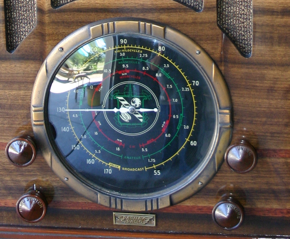
More pictures (2nd one down):
https://www.russoldradios.com/unique-radios.html
Parker made some very nice "farm" radios.
"I just might turn into smoke, but I feel fine"
http://www.russoldradios.com/
Users browsing this thread: 1 Guest(s)
|
|
Recent Posts
|
|
Philco 42-345 Restoration/Repair
|
| Thank you MrFix55 and GarySP with helping with the Antenna, for now I am placing the Antenna on the back burner and work...osanders0311 — 02:24 PM |
|
The list of my radio & TV collection!
|
| Yes, Michael. But strangely enough, I managed to keep the original veneer. I must admit that I don't really like it, so ...RadioSvit — 02:21 PM |
|
The list of my radio & TV collection!
|
| Good radio.
I bet there was a lot of veneer fixing.morzh — 02:16 PM |
|
Philco 46-480 Electronic Restoration
|
| >> it is because I am retired and a little demented.
You have just the right amount of it. No perfectly sane p...morzh — 02:14 PM |
|
The list of my radio & TV collection!
|
| Old Zenith 5S-29 tube radio. First turn-on after repair and reception quality testing. Demonstration of the operation of...RadioSvit — 01:27 PM |
|
Philco 42-345 Restoration/Repair
|
| Welcome to the Phorum, osanders0311! Regardless how far you intend to restore this set, first priority should be replac...GarySP — 11:51 AM |
|
Philco 46-480 Electronic Restoration
|
| Joseph, it is because I am retired and a little demented. My problem is that I wanted to own a collection that spans th...MrFixr55 — 11:29 AM |
|
Philco 46-480 Electronic Restoration
|
| Wow, here I am with only two restored radios. I’ve got to boost those numbers! If you can’t run with the big dogs, you m...jrblasde — 10:04 AM |
|
Philco 46-480 Electronic Restoration
|
| Hello MrFixr55,
That will for sure keep you out of trouble!
Last Sunday was spent mostly doing yard work anyway the we...radiorich — 09:50 AM |
|
Philco 46-480 Electronic Restoration
|
| Throw in all the Audio equipment that has to be kept in a bedroom (my office)L. 8 portable self contained PA speakers, ...MrFixr55 — 07:40 AM |
|
Who's Online
|
There are currently 1167 online users. [Complete List]
» 2 Member(s) | 1165 Guest(s)
|
|
|

|
 
|


![[-] [-]](https://philcoradio.com/phorum/images/bootbb/collapse.png)


