Posts: 2,118
Threads: 112
Joined: Jun 2010
City: Medford OR (OR what?)
Sorry. I am a bad poster. Sometimes I miss old threads.
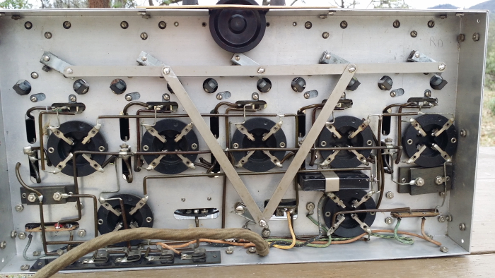
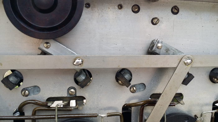
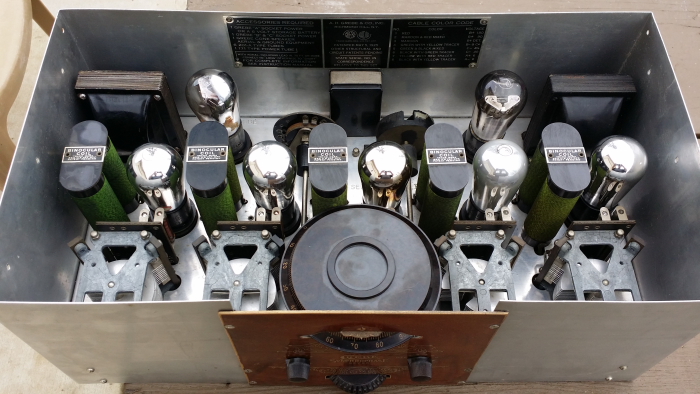
I have a pile of scrap metal. I found a piece of aluminum U channel from which I cut out those arms. They must be all the same or the linkage binds. ALSO, be vey careful in moving stuck linkage. The variable caps are also pot metal. Any additional stress on these and you will have a much bigger problem. I made several extras and selected the ones that fit the best.
Mine moves pretty good using the standard tuning but there is very little friction on the "fine tuning" wheel, so it is mostly for looks.
Note also that I used the original brass shafts and had to use solder to reattach. I suppose that a new shaft could be turned on a lathe, but again care must be used not to put stress on the caps.
"I just might turn into smoke, but I feel fine"
http://www.russoldradios.com/
(This post was last modified: 03-15-2018, 11:15 AM by Phlogiston.)
Posts: 1,199
Threads: 49
Joined: Oct 2017
City: Allendale, MI
U channel - good thought! Right now I'm working on bending brass strap. I hope to make that work. But if it doesn't, I'll look into the channel idea.
I was curious about the solder as my Grebe used (or at least does now) 10/32 screws and nuts, which is the way I'm going to do it. I'm not sure how many modifications were made in the past.
All of my tuning caps rotate very easily so I'm hoping for a smooth system. This reciever does not have a course and fine tuning system, but there is a friction wheel that turns inside the tuning dial. It looks like it could be the same as your fine tuning system. I'm a little concerned about the amount of friction that is there to turn the entire assembly. the AC Six, though, only has 4 tuning caps, so that may be a help compared to your 5.
By the way, where did you get the brown cloth sleve for the wire bundle?
Thanks for your help!
(This post was last modified: 03-15-2018, 09:39 PM by rfeenstra.)
Posts: 1,400
Threads: 46
Joined: Nov 2017
City: Menlo Park
State, Province, Country: CA
Thanks for the explanation on the transformer. I see how the laminations work now 
50 layers is quite daunting, especially with #40 wire. If I remember correctly, the Philco interstage had 24 + 17 layers, primary + secondary. Best of luck whatever you do.
I don't hold with furniture that talks.
Posts: 4,930
Threads: 54
Joined: Sep 2008
City: Sandwick, BC, CA
Those later Grebe models sure took a downward slide in build quality compared to the MU-1 Synchrophase of a few years earlier, pot metal may or may not be a problem in the frame of a tuning condenser, but making a linkage out of it is just asking for trouble no matter how sound the mix is. Even if it doesn't warp or start flaking apart it doesn't wear well. Fortunately it looks like they only used the pot metal for the end plates and used rods and spacers to hold the assembly together, used Bakelite or phenolic strips to mount the stators, and didn't use pot metal in the rotor portion either, so a Majestic or Crosley style failure isn't as likely. Even if they had been buggered up it may be possible to use an A.K model 40 style parts set as an organ donor since the caps are all single section and not ganged.
Regards
Arran
Posts: 1,199
Threads: 49
Joined: Oct 2017
City: Allendale, MI
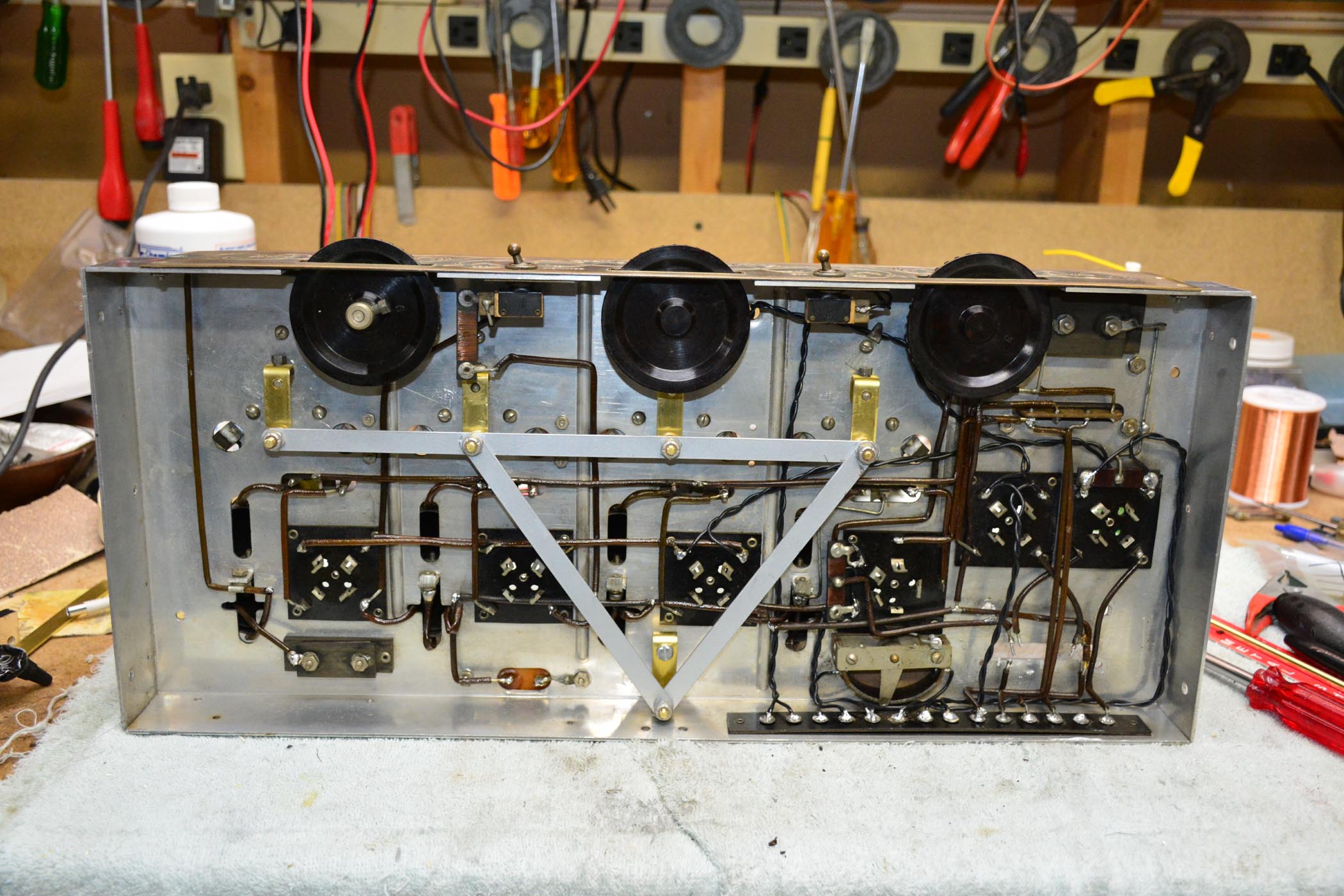
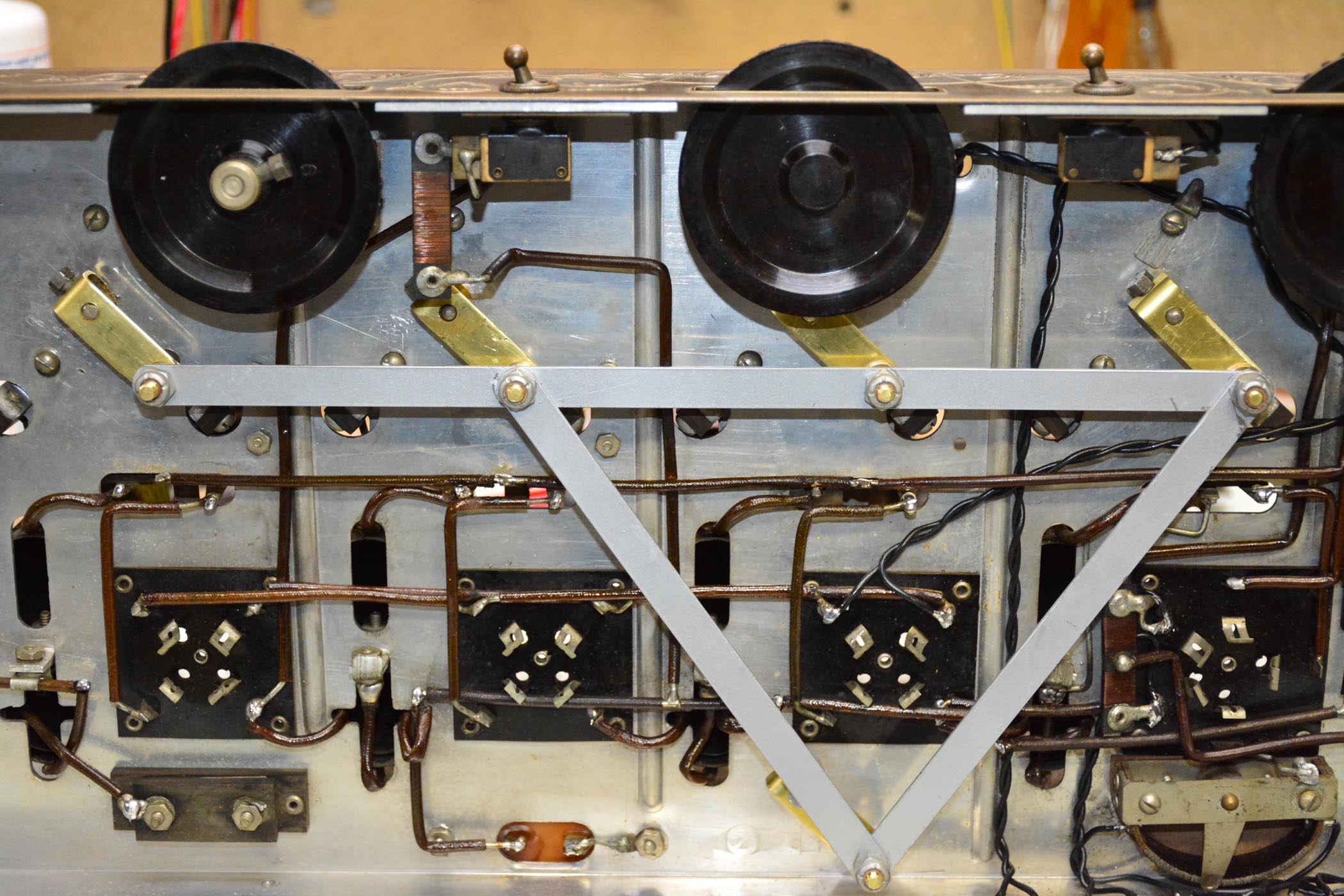
The end plates of the tuning caps are not held apart with a spacer. The end plate castings actually meet in the middle. One of the "spacers" is threaded on the end, the mate from the other end plate is drilled and a screw goes through to the threaded end. Deterioration of the pot metal could cause the whole thing to fall apart. I managed to make new linkages for the assembly out of brass strap using a jig to make sure the holes on each linkage are exactly the same distance apart. If they weren't, the whole thing would bind. There's some advantage to the older chain method of tying the caps together! Hysteresis is probably greater, though. I'll post pics when I get the linkage finished. I need to find some #10 screws with a slight sholder for the brass bearing to ride on. Don't want it to ride on threads as the pot metal linkage did (unless that was not original.) Russ's had some kind of brass pins for the bearing.
(This post was last modified: 03-16-2018, 12:30 AM by rfeenstra.)
Posts: 2,118
Threads: 112
Joined: Jun 2010
City: Medford OR (OR what?)
Yes mine had brass pins - no threads, and the ends were peened like a rivet into the linkage. I cut off the end and when reassembled, used solder to hold it in place.
"I just might turn into smoke, but I feel fine"
http://www.russoldradios.com/
Posts: 1,199
Threads: 49
Joined: Oct 2017
City: Allendale, MI
You know, mine may have been that way originally as I can see tell tail signs of perhaps some grinding in a couple of places on the linkages. I just thought it was wear or manufacturing marks. Interesting! I'll probably just continue to use the nut and screw routine as that looks the easiest to me right now. I have to find screws with a little bit of shoulder cuz I don't want the new brass linkages turning on threads. Hopefully I can make it all work smoothly.
Posts: 1,199
Threads: 49
Joined: Oct 2017
City: Allendale, MI
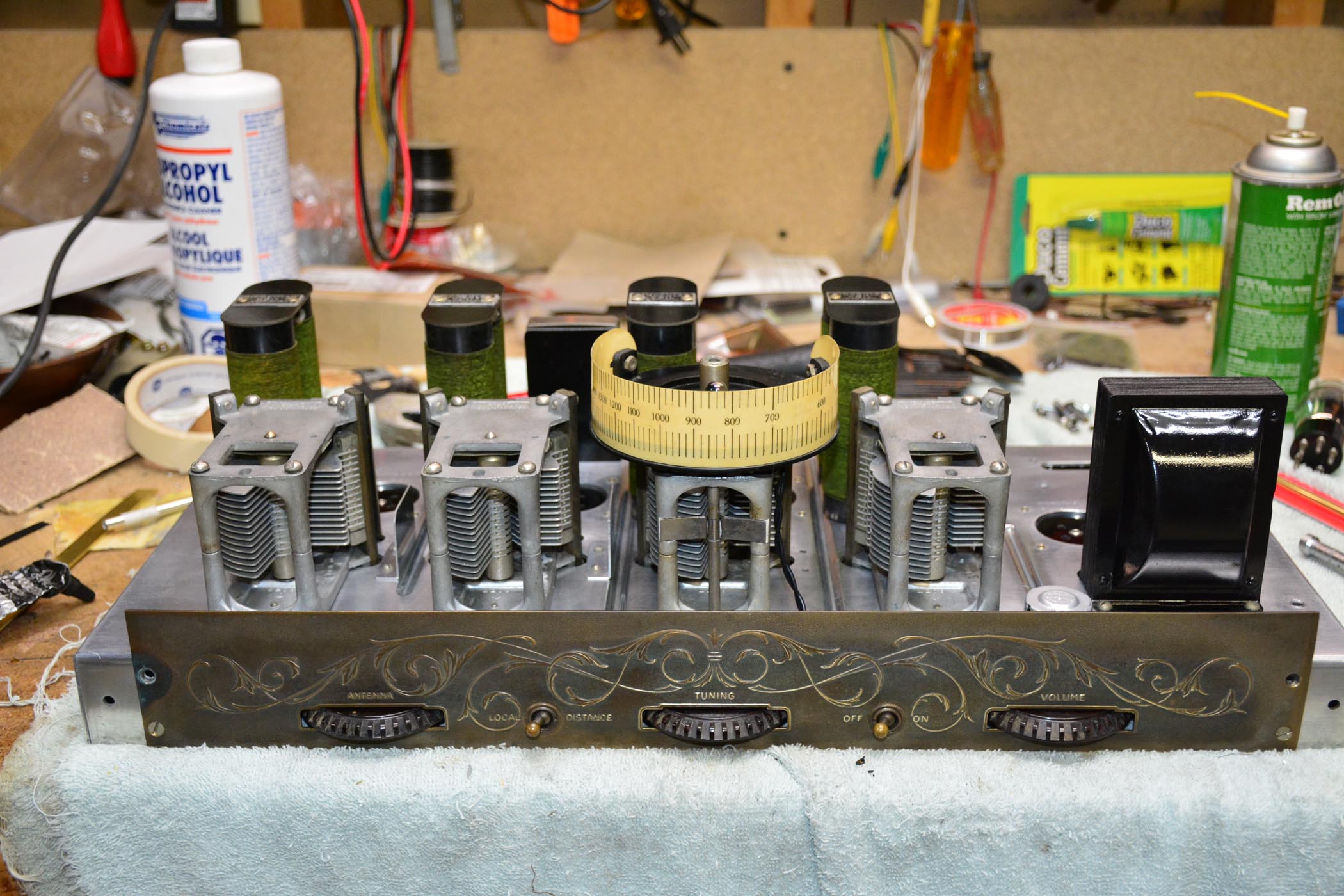
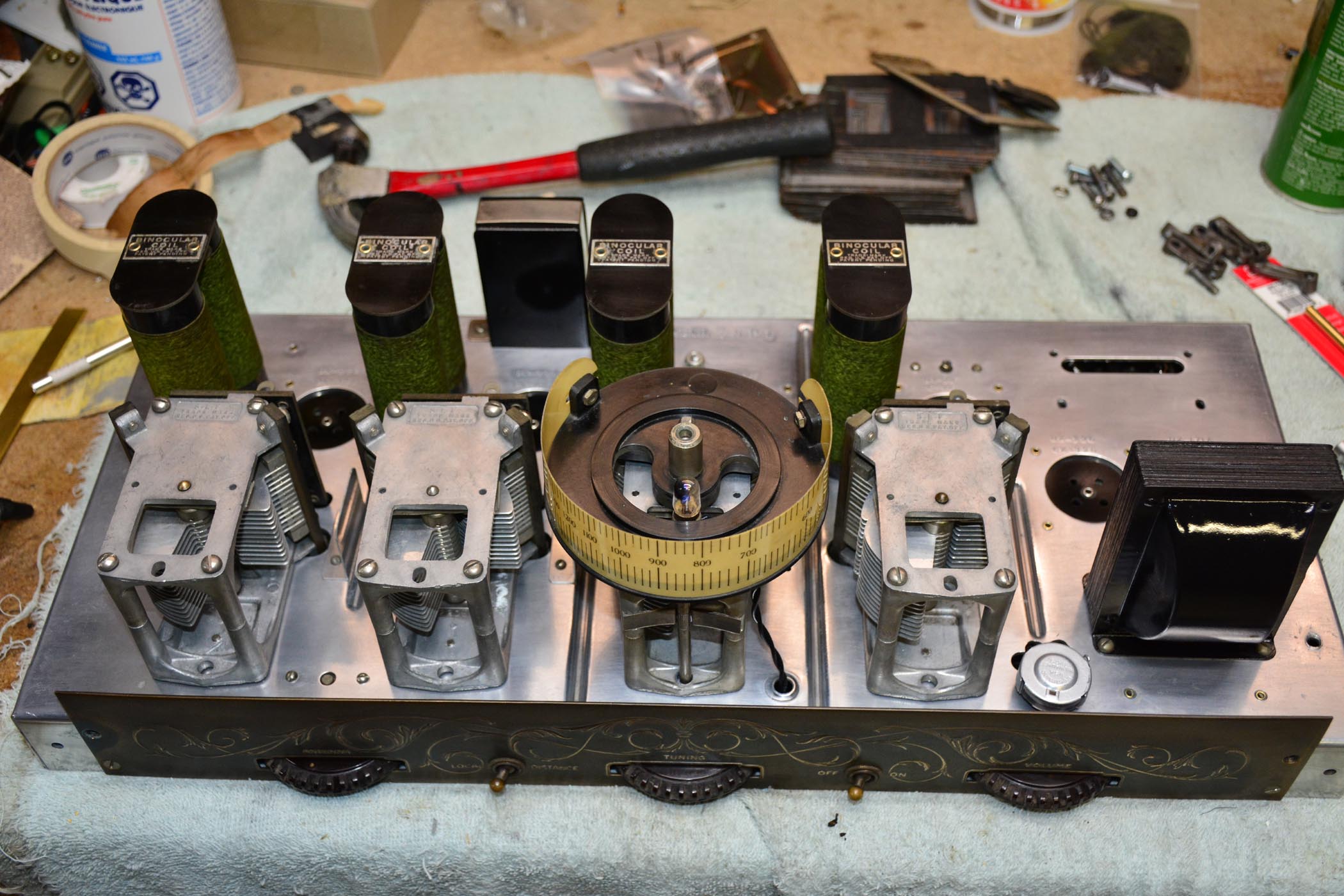
Here's a phew photos of the chassis with the linkage hooked up and WORKING. The brass parts are what I had to make. First attempt is not perfect but works great. I don't think there will be attempt #2.
Next is the TR. I'm gonna unwind, then decide if I want to re-wind.
Notice that the volume control is not original and they hacked up the hole for the wires to make the replacement easier to solder in.
Posts: 1,199
Threads: 49
Joined: Oct 2017
City: Allendale, MI
16500 turns on 52 layers of #40 magnet wire. Ouch!! Of course, the break was right at the connection on the inside of the coil. Interestingly, the wire was spliced in layer 8 from the outside. thought maybe it was a bad splice, but not the case. it was obviously a new spool of wire as the color changed. This splice was within a few turns of the previousl layer. when I uncovered that next layer, there were maybe 20 turns with no insulation - bare copper. I could lay my meter leads across them and read the short. Does anyone know what that would have done to the audio in that transformer? Would it have reduced signal level significantly by sucking up some of the magnetic field? I'm interested to know!
Posts: 1,400
Threads: 46
Joined: Nov 2017
City: Menlo Park
State, Province, Country: CA
Wow! That is quite the winding... The effect of the shorted turns is an interesting thought. It could have reduced the audio, or if might also bog down the previous stage resulting in distortion as well.
I don't hold with furniture that talks.
Posts: 1,199
Threads: 49
Joined: Oct 2017
City: Allendale, MI
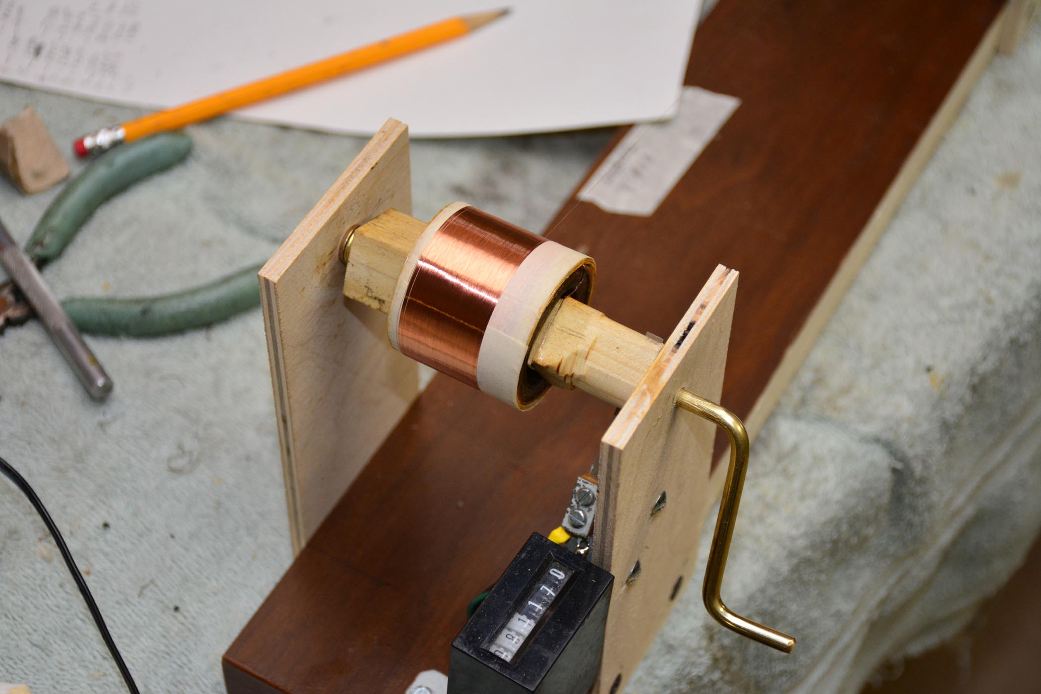
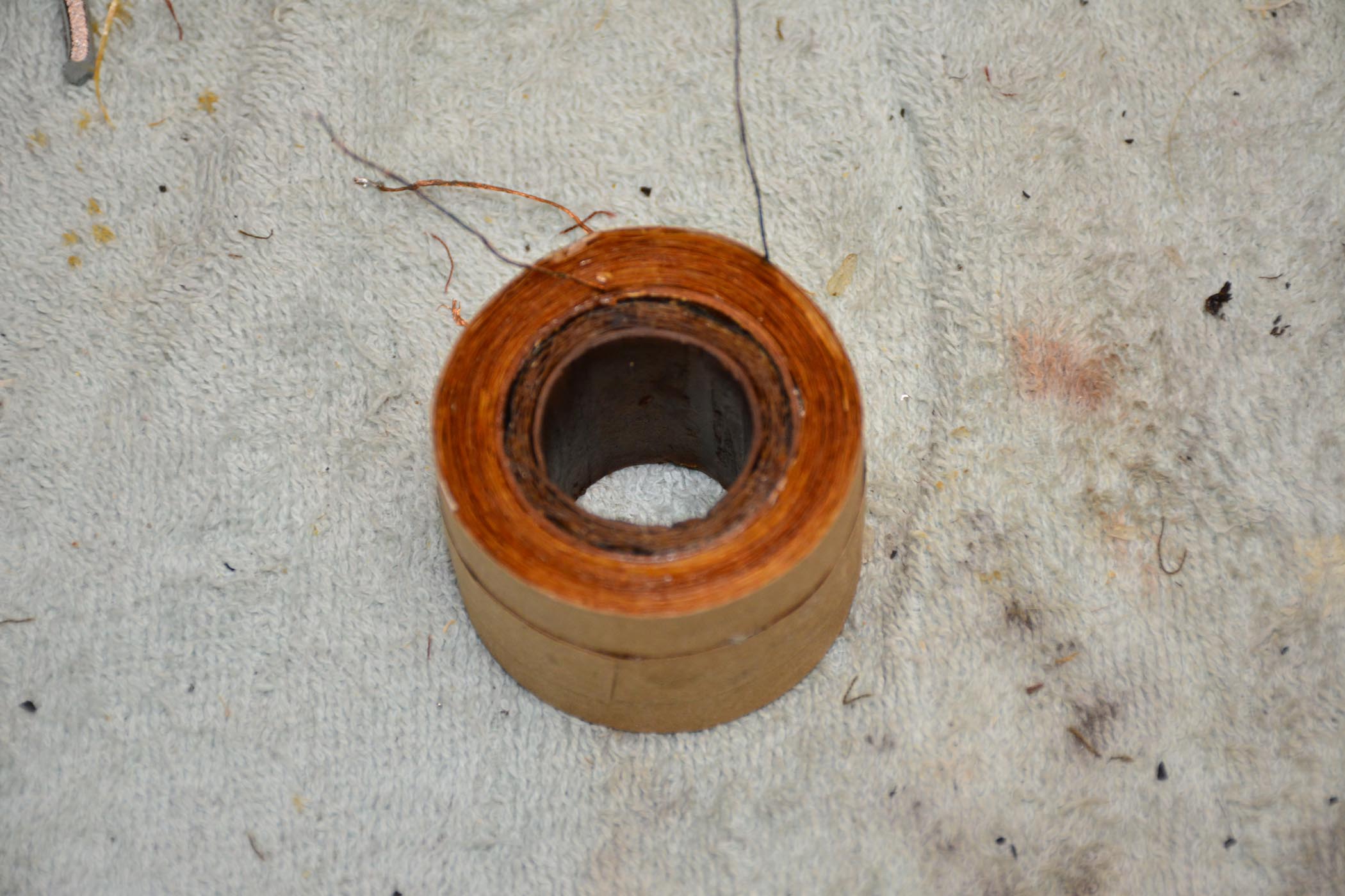
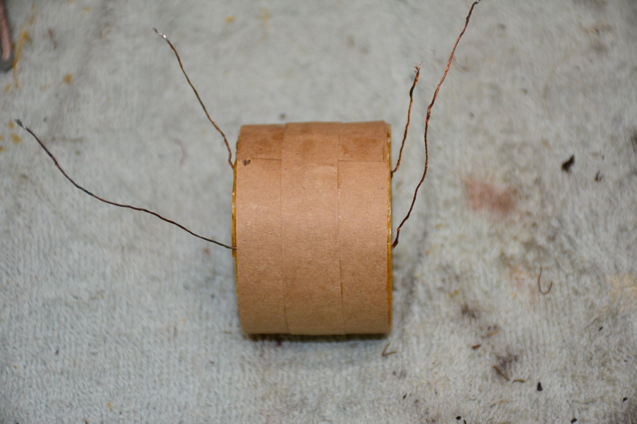
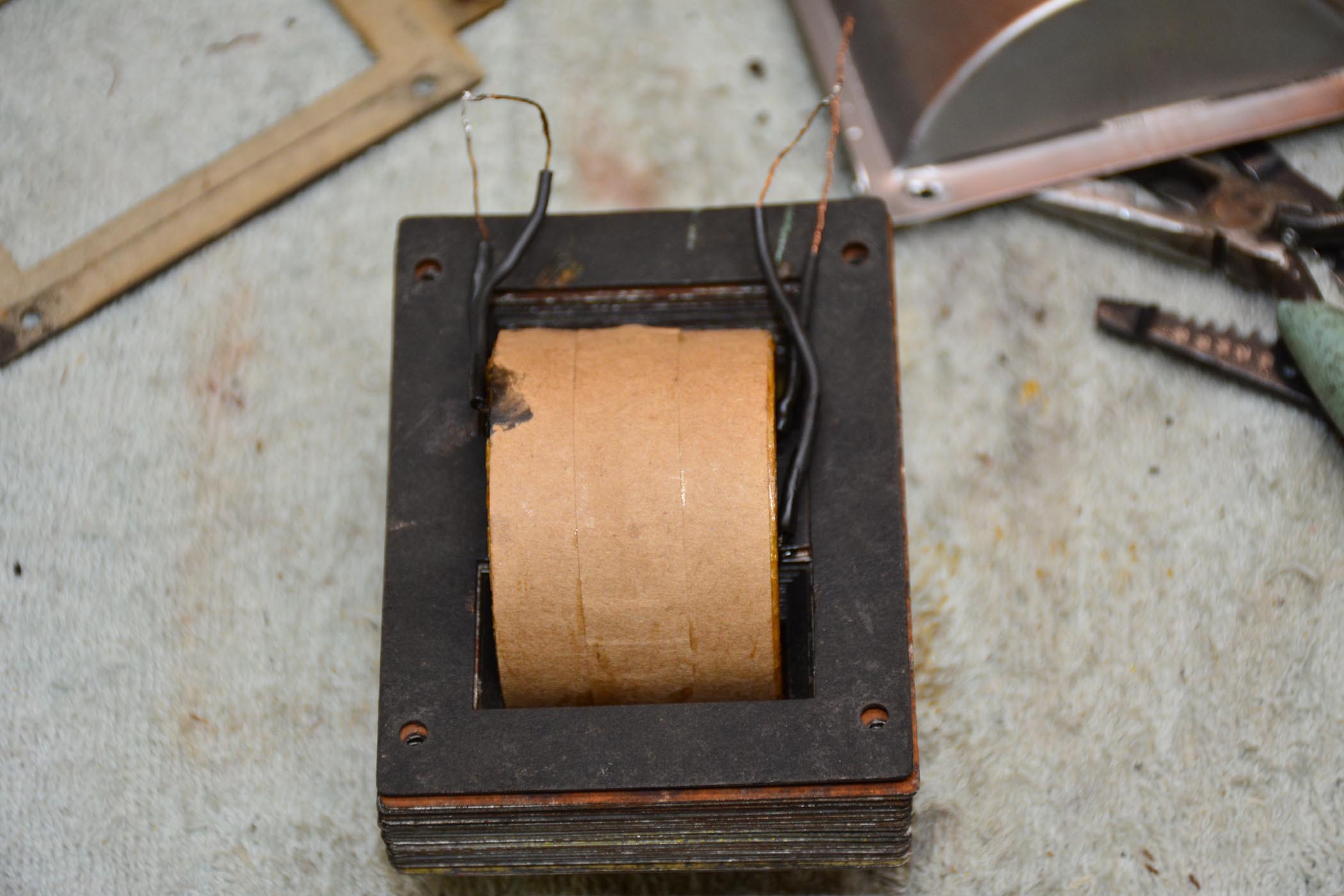
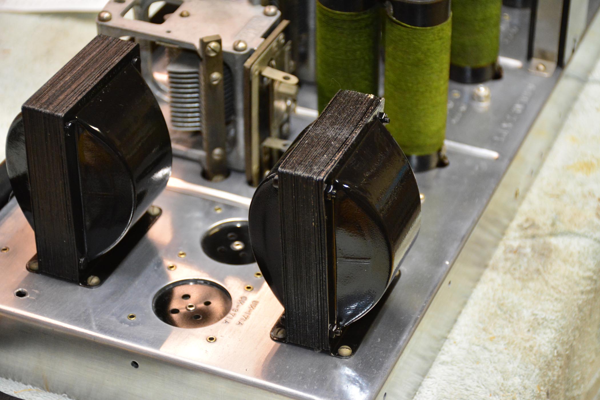
Well, it's finished. 16500 turns. Painful, but done. here's a couple of photos.
In process - somewhere aroung 5000 turns:
Core finnsihed:
final resting place:
(This post was last modified: 03-19-2018, 01:23 AM by rfeenstra.)
Posts: 481
Threads: 18
Joined: Jan 2013
City: Mesa, AZ
Beautiful work on an interesting radio! Did you really crank that little handle on the winder 16,500 times???  I commend you, sir 
Posts: 1,400
Threads: 46
Joined: Nov 2017
City: Menlo Park
State, Province, Country: CA
Gorgeous job, well done Sir 
I don't hold with furniture that talks.
Posts: 1,475
Threads: 69
Joined: Nov 2012
City: Kansas city, MO.
Posts: 599
Threads: 24
Joined: Jan 2014
City: Edmonton AB CA
Great job, unreal patience.
Gregb
Users browsing this thread: 1 Guest(s)
|
|
Recent Posts
|
|
[split] New member...
|
| Well, with the replacement tuning assembly, I have finally put the unit back together and aligned the dial. The first s...HowardWoodard — 01:01 AM |
|
Philco Model 16 wiring question
|
| Well, finding a short is easy.
Like I said, disconnect the transformer's secondary windings and see if it persists.
If...morzh — 09:48 PM |
|
Restoring Philco 96
|
| Nice one!Stan the Man — 09:37 PM |
|
Restoring Philco 96
|
| I have eventually replaced the speaker and shot the video, which only shows the upper part of the dial as the hum is ver...morzh — 09:24 PM |
|
Rogers Majestic R-646
|
| Kinda weird to see both open
Nothing weird if you remember that this radio is about 100 years old :)Vlad95 — 07:49 PM |
|
Philco 42-345 Restoration/Repair
|
| I believe I'm making progress, resistors have been rechecked and corrected, removed that ugly blue capacitor and more wi...osanders0311 — 07:38 PM |
|
Philco Model 16 wiring question
|
| Thanks Morzh
Yes I recapped everything and replaced almost all the resistors as well. I redid #99 with .015 safety ca...bobclausen — 07:11 PM |
|
Philco Model 16 wiring question
|
| Well...pull out every single load of the transformer. For every winding.
Unsolder if needed.
Then re-do your dim bulb....morzh — 07:02 PM |
|
Rogers Majestic R-646
|
| Kinda weird to see both open, but once you get it up and running, really pay attention to your sound. Listen for loud cr...TV MAN — 06:59 PM |
|
Rogers Majestic R-646
|
| Vlad;
I was just reminded of something else, I'm not sure why but many Rogers built sets do seem to have open primari...Arran — 04:40 PM |
|
Who's Online
|
There are currently 823 online users. [Complete List]
» 1 Member(s) | 822 Guest(s)
|
|
|

|
 
|


![[-] [-]](https://philcoradio.com/phorum/images/bootbb/collapse.png)


