Scott 16 - Restoration Begun
Posts: 1,199
Threads: 49
Joined: Oct 2017
City: Allendale, MI
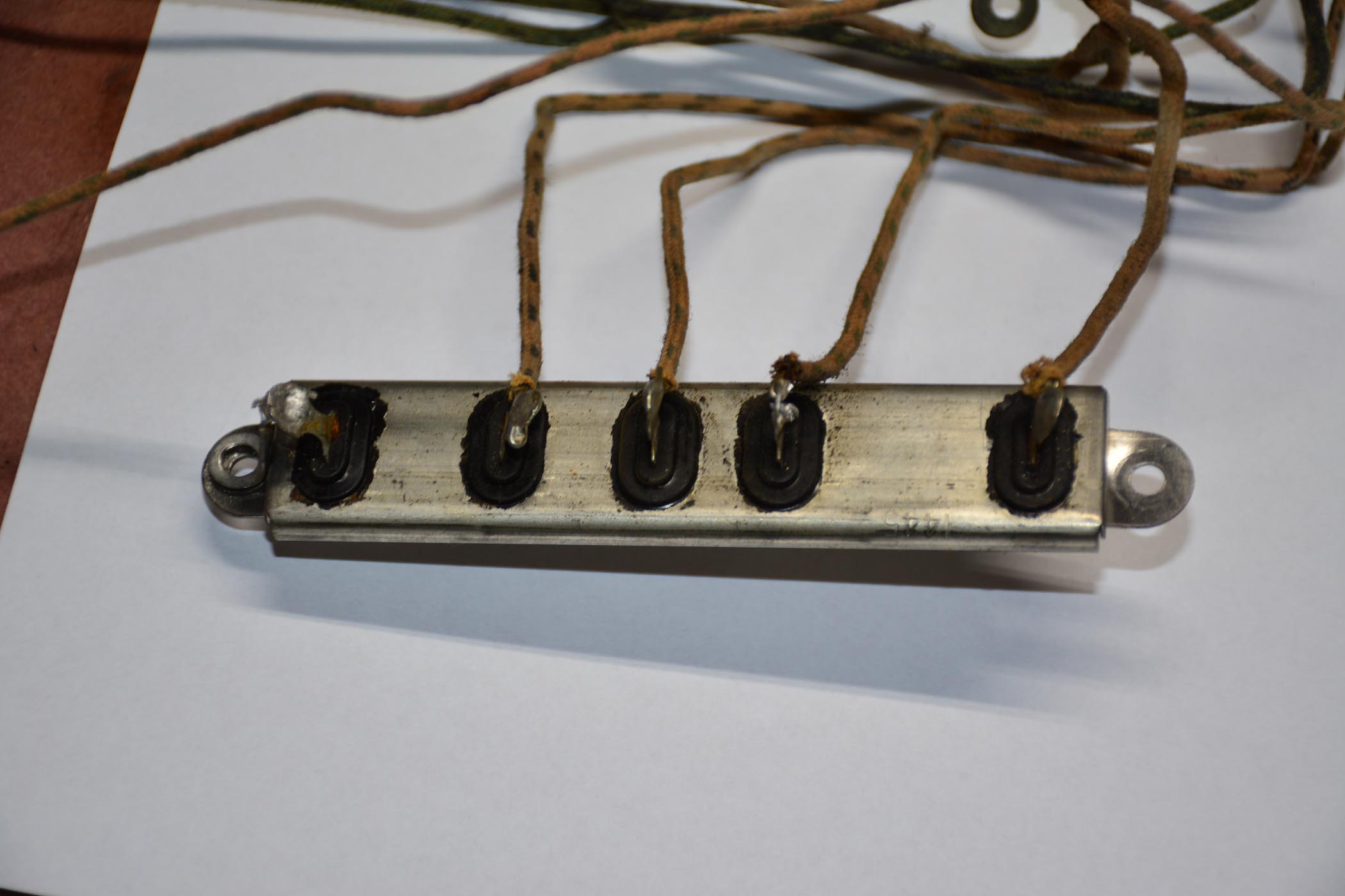
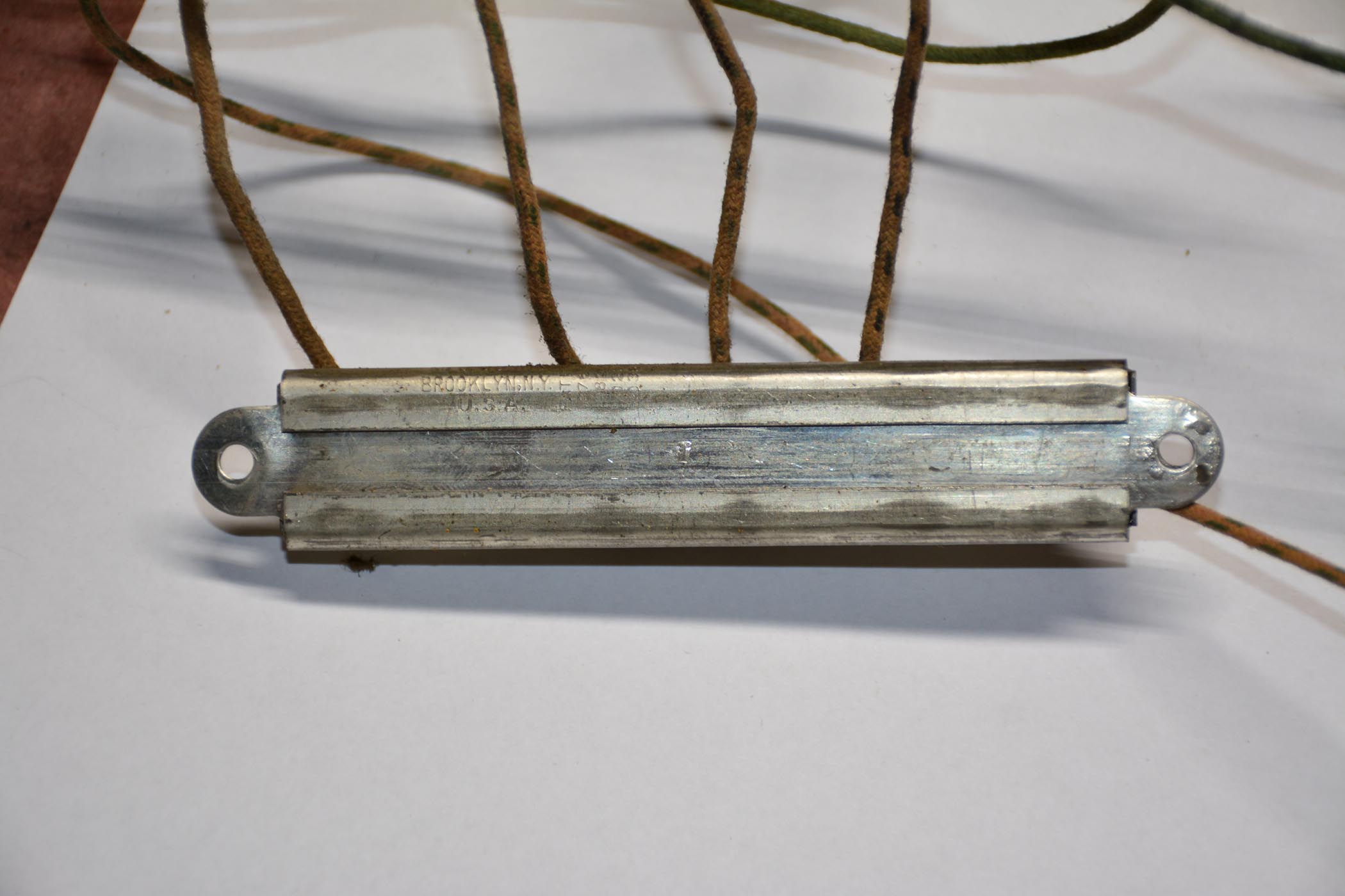
This one doesn't have the normal seam to get a knife through to cut the windings. My concern with using the good sections are the very connections you mentioned. As you say, the taps are pressed onto the resistance wire, leaving the great possibility of future failure at the remaining crimped connections. The more I consider it, the more inclined I am to disable all sections and use the taps as terminals for the Dale resistors that I have ordered. Disabling the sections will require taking the candohm apart and then bending it back together, as you can see in the photos. Not a big problem, just need to be sure the terminals are well insulated.


Posts: 2,118
Threads: 112
Joined: Jun 2010
City: Medford OR (OR what?)
Yes, I see. The metal case is really tough. Let us know how it goes.
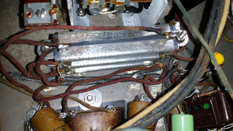
Here is a picture of the stacked candohms in a strat for comparison (seam at the top). In this case the replacement WW resistors are hidden between the stacked originals.

This is a "before" picture.
"I just might turn into smoke, but I feel fine"
http://www.russoldradios.com/
(This post was last modified: 04-23-2018, 10:29 AM by Phlogiston.)
Posts: 1,199
Threads: 49
Joined: Oct 2017
City: Allendale, MI
Nice. I probably won't be able to hide the ww resistors quite so well. There'll be 4 of them. I think, though, that if I keep the 4 resistors all on the same side of the candohm (which is mounted on the side of the chassis) under the wires, they will not be terribly obvious.
I know you have changed a lot of the wire in these things. I will probably change the HV wires for safety reasons but keep the LV stuff as is. The wire is very flexible, but I assume there are breaks in the insulation under the cloth. I don't want the HV to arc through those breaks. I don't think that would be a problem with bias, heater, and other low voltage wire. Your thoughts? Thanks Russ.
Posts: 2,118
Threads: 112
Joined: Jun 2010
City: Medford OR (OR what?)
If the wire feels stiff, if you can hear or feel it break/crack when you bend it, replace the wire. IF not it would pretty much be for looks and longevity, but that is ok too. Old Philco cloth insulated wire seems particularly prone to hardening.
You know that original push-back wire was probably unrated and would never be rated for 600V today (as seen in the strat pic). In the old days I used to turn the chassis over in a dark room and look for aura/arcs. Haven done that for years.
Trying to find a picture of the replacements hanging below the original - -
"I just might turn into smoke, but I feel fine"
http://www.russoldradios.com/
(This post was last modified: 04-23-2018, 01:09 PM by Phlogiston.)
Posts: 1,199
Threads: 49
Joined: Oct 2017
City: Allendale, MI
The out put transformer on this radio was a general replacement that did not match the impedance of the speaker (39 ohms). One of the members on the EH Scott forum kindly supplied an original transformer that had an open primary. Another transformer to rewind! This one is interesting in that the 2 halves of the primary are separated by the secondary windings. Half the primary is wound in the center, then the secondary windings on top of that, then the second half of the primary. Both parts of the primary have the same number of layers and turns, but obviously the outside half of the primary will have considerably more wire and, therefore, higher resistance. The primary resistance for one side is only about 120 ohms. The outside half was the open half so I couldn't measure it but it could wind up being maybe 30% higher. How does this affect the push-pull amplifier? Maybe the actual impedance of the longer half is really not that different than the inside half. Your thoughts on this. I could wind the primary in the "normal" way making the discrepancy somewhat less. One has to assume, though, that Scott had a reason for designing it this way.
Posts: 2,118
Threads: 112
Joined: Jun 2010
City: Medford OR (OR what?)
That was, at least an attempt at a better transformer. You could wind it with the primary entirely on the inside (conventional). Or you can do it like it was. Sounds like you only need to rewind the outside section, which, I'll bet, was the same value(s) as the inside section. Either way, you will probably not be able to tell the difference.
Some audio transformers were wound side-by-side attempting to get better response.
"I just might turn into smoke, but I feel fine"
http://www.russoldradios.com/
Posts: 1,199
Threads: 49
Joined: Oct 2017
City: Allendale, MI
Thanks Russ. I've rewound the inside as well. I figured that as long as I was in there, I might as well do it right. In unwinding the outside primary section, the wire broke very easily several times (34 awg). Given that, I took the decision to do all of it as I thought maybe the wire had deteriorated somehow. In unwinding the inside of the primary, I even had that wire break once and there really was very little stress on it as I unwound it. Now I know it will be good!
Posts: 2,118
Threads: 112
Joined: Jun 2010
City: Medford OR (OR what?)
Most likely corrosion had some impact. It might also have been overheated at some point. The materials used in construction, like solder flux and glue from tape can be very corrosive. That is why many of the breaks are at the solder joints.
"I just might turn into smoke, but I feel fine"
http://www.russoldradios.com/
Posts: 1,199
Threads: 49
Joined: Oct 2017
City: Allendale, MI
Posts: 4,460
Threads: 423
Joined: Jun 2011
City: Boston
State, Province, Country: Massachusetts
That is pretty, I would be afraid to work on it!
Paul
Tubetalk1
Posts: 1,199
Threads: 49
Joined: Oct 2017
City: Allendale, MI
Yes it is! My biggest concern is scratching it during the riveting process.
Posts: 2,118
Threads: 112
Joined: Jun 2010
City: Medford OR (OR what?)
Hit that sucker with a hammer - HARD! Just don't miss the rivet.
I have a piece of foam that I put on the bench to work on these. But, you need a dense, hard surface to drive the rivets. I have an old delta table saw with a SOLID steel top, great for pounding rivets.
"I just might turn into smoke, but I feel fine"
http://www.russoldradios.com/
Posts: 330
Threads: 30
Joined: Aug 2017
City: Hay Lakes, Alberta,Canada
Wow!!! Need sunglasses...
Now that we've entered a riveting conversation about riveting...When radios were assembled at the factory, they used special tools/machines to do the riveting process. Does anyone have any such tools? Of pictures of what they looked like? I've tried to find specific tools for years...anyone I talk to in the supply industry looks at me with blank stare, and then points me to pop rivets.
Posts: 1,199
Threads: 49
Joined: Oct 2017
City: Allendale, MI
Russ, that's what I did on the power supply. I'm just not very good with a hammer! No practice.
As far as the tools are concerned, I have the setting tool for the semi hollow rivets. As Russ said, hit it hard with a good backing and don't miss. I also have an aviation hand rivet press with the proper dies. This works for rivets that are on the side within 3" of the edge of the chassis. They press very nicely. Unfortunately, most of the rivets cannot be reached with this tool, so it's back to the hammer routine. Since some of the rivets hold up to 4 pieces, it will be a challenge to hold everything in place as I wack it with the hammer! I'm sure the factory had a pneumatic rivet press that had a deep enough throat to handle the entire chassis.
Posts: 1,824
Threads: 114
Joined: Jul 2014
City: Sneedville, TN
I know it isn't original, but I just replace the rivets with little pan head screws, internal lock washers, and little hex nuts. Less chance of damaging anything putting them in, and you don't need special tools. Of course, someone really picky may notice it, but that's THEIR problem for being too anal about such things. It's how we did it back in the day, and it's good enough for me now.
Users browsing this thread:
|
|
Recent Posts
|
|
Philco newbie with P-1891-WA console questions
|
| Hello Jeff ,
Far as the Electrolytic capacitors go here is a list of parts.
that will work . I like using Nichicon and...radiorich — 09:50 PM |
|
Philco newbie with P-1891-WA console questions
|
| Well, I've been stumped at trying to get the first of 11 electrolytic capacitors. I got a schematic and have a list of t...Jeffcon — 07:54 PM |
|
Model 80 Antenna Issue?
|
| Thanks Gary and Rod.
I also found an article in the Philco Repair Bench under Service Hints and Tips, about installi...Hamilton — 12:32 PM |
|
Model 80 Antenna Issue?
|
| Hello Hamilton, here is a little information found in our Philco Radio Library at the bottom of the Home page. Hope it ...GarySP — 11:28 AM |
|
Model 80 Antenna Issue?
|
| I did as you suggested and touching the middle of the volume control did nothing so the coil has to be rewound. Any idea...Hamilton — 10:19 AM |
|
1949 Motorola 5A9M
|
| This would be the second portable in the "other radios" forum where I have a similar one in my collection. I h...Arran — 12:41 AM |
|
Looking for any info: 1977 Ford-Philco Console Hi-Fi Turntable and Radio
|
| Hi PittsburgTost.
The record changer looks like a Garrard or BSR (Likely Garrard). The spindles just pull out and pu...MrFixr55 — 11:57 PM |
|
Looking for any info: 1977 Ford-Philco Console Hi-Fi Turntable and Radio
|
| Hello PittsburghToast ,
Welcome aboard and it looks like gary may have something for you !
now if I dig through my se...radiorich — 11:35 PM |
|
Model 80 Antenna Issue?
|
| You are kind of on the right path. You can touch the grid cap of the Detector/Oscillator 36 tube. I'm expecting a respon...RodB — 08:48 PM |
|
Looking for any info: 1977 Ford-Philco Console Hi-Fi Turntable and Radio
|
| Welcome to the Phorum, PittsburghToast! I found an old thread that my interest you regarding the quality and worth of P...GarySP — 08:48 PM |
|
Who's Online
|
| There are currently no members online. |

|
 
|


![[-] [-]](https://philcoradio.com/phorum/images/bootbb/collapse.png)


