1934 Philco 60B Alignment Problem
Posts: 38
Threads: 5
Joined: Feb 2017
City: manhattan beach, CA
At work, I've been fiddling with this Philco 60B, second version, this week. It plays loud and clear and sometimes too loudly on the strong stations but it's main problem is that I can't align the stations to the dial. The spread is too wide for the dial by about 100khz or so. I run out of trim on the trimmer caps to get the frequencies within the dial. I'm using John Rider's "Aligning Philco Receivers", page 76 as reference. The sensitivity of the AM broadcast appears to be good. I can go down to 5uV and still hear the 400hz tone from the HP Rf generator. The Police/Shortwave band is another story. I have to turn the signal up into the hundreds of mV's (millivolts) to hear the tone. I've inspected and checked the antenna transformer it looks good and has no open circuit. I replaced the 100k resistor that is across the primary that was out of spec but no improvement. What could cause the wide alignment issue? Is the lack of sensitivity on SW affecting the alignment?
On another question about this radio, there is a inductor coil riveted to trimmer #4, I think. It looks like its connected across this capacitor trimmer. The coil was covered with a white crust that was probably from a leaking wet capacitor that is above it. I can't seem to find this thing on the schematic. Is there a callout on the schematic?
I'm learning a lot from all of you on this phorum, thanks.
Posts: 751
Threads: 91
Joined: Nov 2015
City: Jonesboro
State, Province, Country: AR
Check out Ron's write-up on the history and changes on the 60 here. You might find what you're looking for here, as far as the mystery part.
http://philcoradio.com/phorum/showthread.php?tid=15007
Blessings,
Jeff W.
Jonesboro, Arkansas
http://jeffsradios.weebly.com
God loves you as you are, not as you should be, because none of us are as we should be. - Brennan Manning
Posts: 38
Threads: 5
Joined: Feb 2017
City: manhattan beach, CA
Thank you Jeff. That page breaks it all down. My guess is this is run #6 since it has no wave trap but I will confirm when I get to the shop Monday. You can imagine my frustration when the wiring don't match the schematic. Now I suspect the alignment instruction maybe different. This radio was previously recapped except for the micas. I may need to check those too if I can't improve the alignment.
Posts: 38
Threads: 5
Joined: Feb 2017
City: manhattan beach, CA
Hmmm, this unit does have a wave trap. It's in the spot where the 600kc trimmer should be. The 600kc trimmer is located where the wave trap should go. I'll provide some photos later. Weird!
Posts: 16,562
Threads: 573
Joined: Oct 2011
City: Jackson
State, Province, Country: NJ
The trap you don't need.
People who do not drink, do not smoke, do not eat red meat will one day feel really stupid lying there and dying from nothing.
Posts: 38
Threads: 5
Joined: Feb 2017
City: manhattan beach, CA
(04-30-2018, 04:12 PM)morzh Wrote: The trap you don't need.
Yes, I know.
Did an alignment. It's still not right. One problem is the plastic dial face is warped all over so tuning will be challenging. I remember seeing a post on this forum about flattening the dial.
There is a spot on the dial where there is a loud pop or crackle. It's the same spot for both AM and SW. Is that caused by the plates shorting against each other on the tuning capacitor?
(This post was last modified: 04-30-2018, 09:45 PM by whirligig.
Edit Reason: photos
)
Posts: 16,562
Threads: 573
Joined: Oct 2011
City: Jackson
State, Province, Country: NJ
Yes, it is likely there is shorting of the vanes. Or maybe a piece of dirt. Give it a good blast of compressed air.
People who do not drink, do not smoke, do not eat red meat will one day feel really stupid lying there and dying from nothing.
Posts: 7,305
Threads: 270
Joined: Dec 2009
City: Roslyn Pa
You can check itw/an ohm meter BUT most of the time it's in parallel w/a low resistance coil (like 3 or 4 ohms) so what you a looking for is very low resistance if the plates are rubbing (like .1 ohm). A few ohms is pretty normal.
GL
When my pals were reading comic books
I was down in the basement in my dad's
workshop. Perusing his Sam's Photofoacts
Vol 1-50 admiring the old set and trying to
figure out what all those squiggly meant.
Circa 1966
Now I think I've got!
Terry
Posts: 38
Threads: 5
Joined: Feb 2017
City: manhattan beach, CA
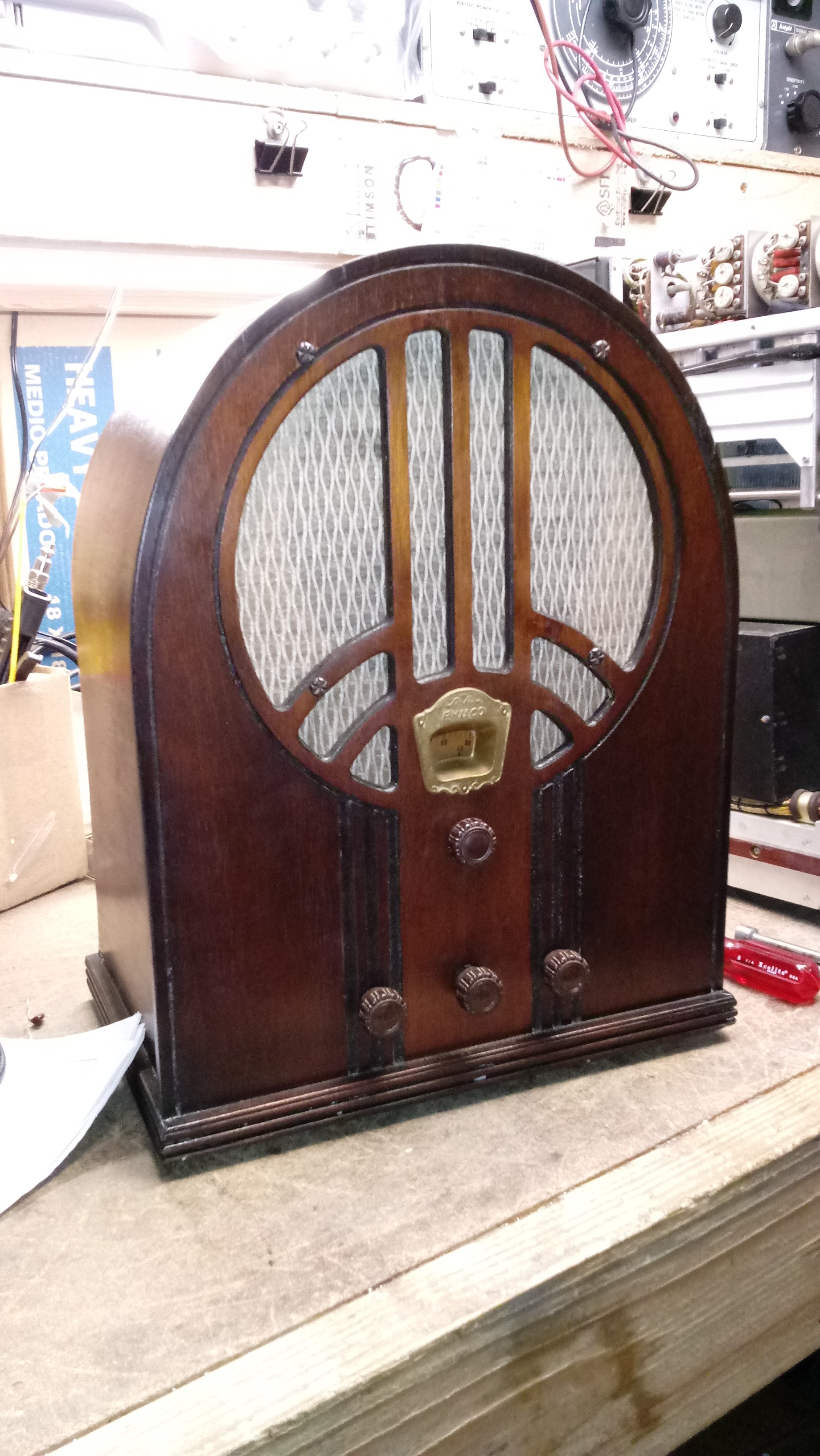
This is the 60B I've been working on.

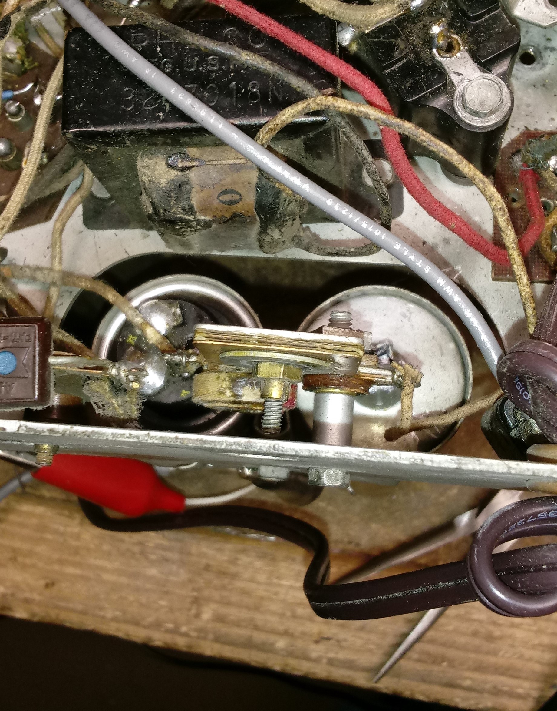
This is the wavetrap that was located in the spot where the 600kc trimmer should be.

This is the 600kc trimmer (shiny brass nut) underneath the #20 condenser package.

Posts: 7,305
Threads: 270
Joined: Dec 2009
City: Roslyn Pa
I have a question, on the dial it has the calibration of both the bc band and the sw band. What frequencies does the sw band cover?
When my pals were reading comic books
I was down in the basement in my dad's
workshop. Perusing his Sam's Photofoacts
Vol 1-50 admiring the old set and trying to
figure out what all those squiggly meant.
Circa 1966
Now I think I've got!
Terry
Posts: 38
Threads: 5
Joined: Feb 2017
City: manhattan beach, CA
I'll send a photo of the dial when I get in to work tomorrow. I need to open her up and clean out the tuner. I recall 1.5mhz on the lower end but the upper end could be 2.4 or 4mhz. We'll see.....
Posts: 7,305
Threads: 270
Joined: Dec 2009
City: Roslyn Pa
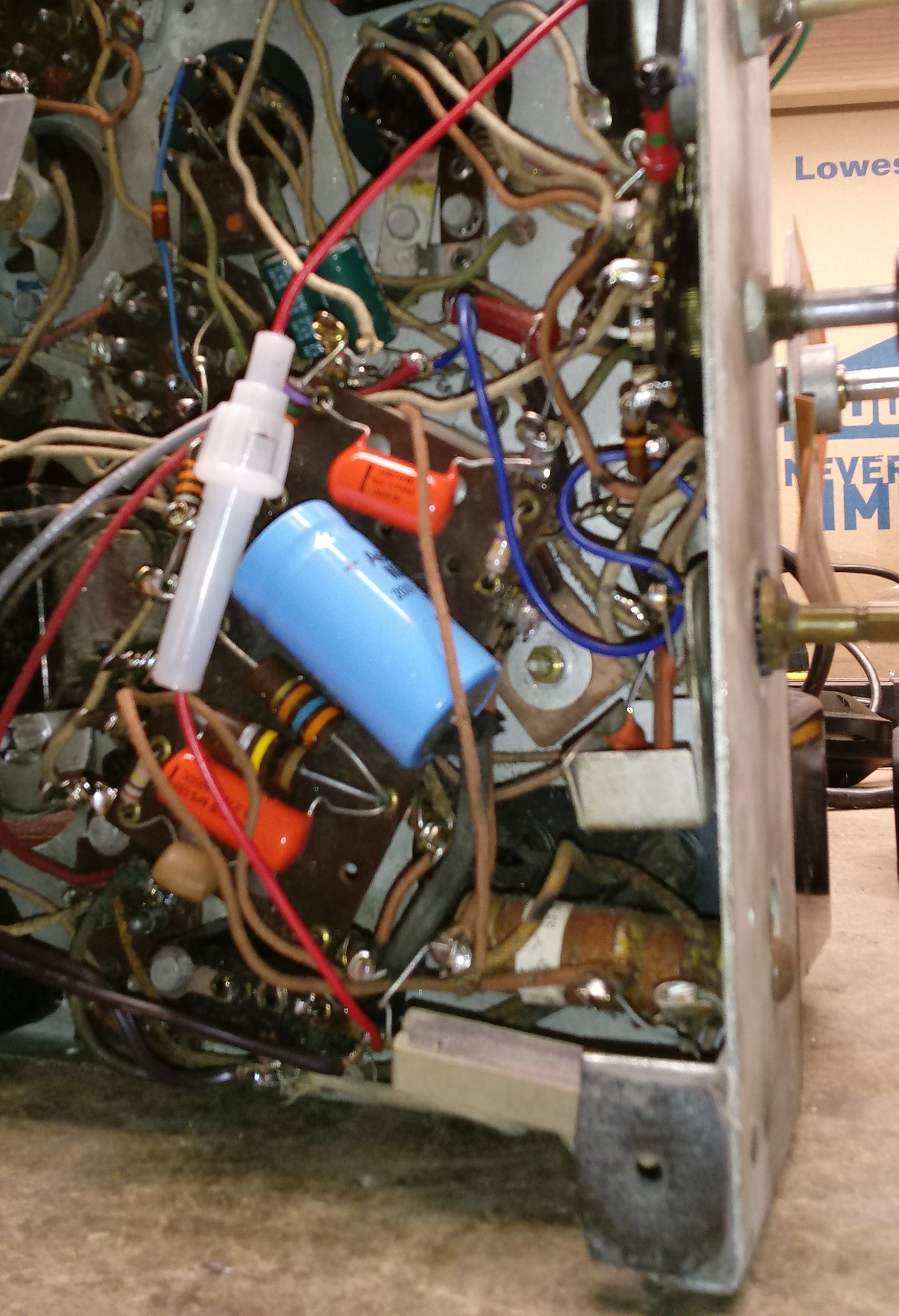
The reason I asked is that the bottom of the chassis looks like a 66. Haven't seen a 60 w/a terminal board. I'm no expert on these things.
When my pals were reading comic books
I was down in the basement in my dad's
workshop. Perusing his Sam's Photofoacts
Vol 1-50 admiring the old set and trying to
figure out what all those squiggly meant.
Circa 1966
Now I think I've got!
Terry
Posts: 13,776
Threads: 580
Joined: Sep 2005
City: Ferdinand
State, Province, Country: Indiana
Terry is correct. That is a 66 chassis. Model 60 sets do not have the terminal board, nor do they have a choke under the chassis. The 66 has both.
--
Ron Ramirez
Ferdinand IN
Posts: 38
Threads: 5
Joined: Feb 2017
City: manhattan beach, CA
Just reviewed the Philco 66 schematic from Nostalgia Air and the layout looks just like the radio I've been aligning. I need to get to the bottom of this when I get to the shop in the morning.
Posts: 7,305
Threads: 270
Joined: Dec 2009
City: Roslyn Pa
[Image: http://philcoradio.com/phorum/images/smi...iggrin.gif] Yay !! I got one right!! They say a blind squirrel gets a nut every once in a while.
The top of the chassis looks identical but the frequency coverage and dial are different. The underside looks pretty different.
Here's a 66 I did a few months ago, before pic.
[Image: http://philcoradio.com/phorum/attachment.php?aid=14642]
After
[Image: http://philcoradio.com/phorum/attachment.php?aid=14643]
When my pals were reading comic books
I was down in the basement in my dad's
workshop. Perusing his Sam's Photofoacts
Vol 1-50 admiring the old set and trying to
figure out what all those squiggly meant.
Circa 1966
Now I think I've got!
Terry
(This post was last modified: 05-02-2018, 11:46 AM by Radioroslyn.)
Users browsing this thread:
|
|
Recent Posts
|
|
Rogers Majestic R-646
|
| Today I finished inspecting all the parts. The result is not very pleasing.
The first positive news:
1) The power tr...Vlad95 — 11:40 PM |
|
HiFi (Chifi) tube amp build - but my own design.
|
| Well, found muh culprit. After using socket test adapters and finding voltages all ok, swapping 6V6s, no avail, swapped ...TV MAN — 11:18 PM |
|
HiFi (Chifi) tube amp build - but my own design.
|
| Well, maybe - maybe not :lol: It's been an interesting project so far! Something so simple, yet so cranky. The 1st one ...TV MAN — 05:12 PM |
|
1949 Motorola 5A9M
|
| Haven't thought of Burgess batteres in a while
https://www.radionostalgia.ca/lib/Images/battery/us/burgess1D.jpgi
...Vlad95 — 03:50 PM |
|
Philco Model 16 wiring question
|
| Measure the voltages first, just in case.morzh — 02:19 PM |
|
1949 Motorola 5A9M
|
| Haven't thought of Burgess batteries in a while Mr. Fixer. Boston Edison always used Burgess in their Bright Star yellow...Paul Philco322 — 02:17 PM |
|
1949 Motorola 5A9M
|
| Thanks Sam. I'll let you know. I can probably scare some up from the local radio club.klondike98 — 02:07 PM |
|
Philco 89 Code 123 Osc Coil
|
| Hello,
I thought I would post my findings on my bad oscillator tickler coil. There were 27 turns on the outer coil b...dconant — 12:38 PM |
|
Philco Model 16 wiring question
|
| Thanks Morzh. So it appears I did wire it incorrectly and I have to switch the wires between pins 2 and 4.bobclausen — 09:24 AM |
|
Philco 46-1209 strange behavior
|
| No, it's not a problem, just during certain condition it could show up.
Yes, an internal tube short could do that too.
...morzh — 09:13 AM |
|
Who's Online
|
There are currently 913 online users. [Complete List]
» 1 Member(s) | 912 Guest(s)
|
|
|

|
 
|


![[-] [-]](https://philcoradio.com/phorum/images/bootbb/collapse.png)


