RCA 110K2 Unexpected project
Posts: 4,707
Threads: 51
Joined: Sep 2008
City: Sandwick, BC, CA
Ed;
This is often the case, once you start poking around under a radio you begin to find stuff that just has to be dealt with. While checking over a new radio I acquired, I started figuring out what I needed to replace, and how to replace it, since the filter caps were shot I thought about replacing those using a terminal strip. Whilst looking at terminal strips, and at possible wiring arrangements for it, I ran across an older unfinished project and decided to work on that first, since it was already out on the bench. So yesterday I worked out a game plan, found a suitable terminal strip, and soldered it under the chassis right next to one of the twist tabs holding the old condenser can in. Then I started on routing the wiring, the wire from the 5Y4 filament to to the former input cap was too short to reach the new terminal, at least 1/2'' too short, then I noticed a 100 Ohm resistor that was supposed to be connected to the output filter cap was measuring up at 1520 ohms, over 50% off spec. Next I need to figure out where to put the bypass electrolytic, it's connected to the screen grids on three tubes, it used to be located in the old can too. Then I looked at the original power cord, it has bare wires showing right where it enters the molded plug, and I will need to replace the crappy wires going to the loop antenna, more work!
The set in question is a Canadian RCA Victor model A-30 from 1940, same era as your 100K2, except it has a single ended output, five bands, and an untuned RF amplifier stage. I don't know if your set used this style of socket but the terminals under the tube sockets are actually forked, no holes, when you want to attach a wire or a component lead, you spread the middle section of the fork apart from the two outside sections with a thin screwdriver, stuff the lead or wire in-between, pinch the sections slightly closed, then solder, you don't have to wrap the wire around the terminal like one with holes. Having a solder sucker is really useful for cleaning these or any other terminal off, saves lots of time. I've never had an RCA or G.E set (both are similar in Canada) that was a dog in terms of performance, even the five tube ones, they seemed to design and build their tubed circuits and parts rather well.
Regards
Arran
Posts: 1,288
Threads: 44
Joined: Nov 2017
City: Menlo Park
State, Province, Country: CA
Hi Arran,
Alas, the tube sockets on this set have 2 holes in each tab for the soldered connections. A bit of care is needed to follow the original placement of wires so that component leads have a place to go later. The forked style would make things much easier.
Looks like otherwise we're on fairly parallel paths. I replaced the loop antenna wiring, as this was completely frayed and presented bare wires where they passed into the chassis. Not surprising, as there is no grommet or other protection from the punched edges of the metalwork. The same condition, with extra hazard, is presented at the other side of the chassis where the feed to and from the speaker and output transformer pass. That bundle has ~285 V present in operation!
The good news is that things are going in the right direction, and that it doesn't matter how long it takes.
Cheers
Ed
I don't hold with furniture that talks.
Posts: 4,707
Threads: 51
Joined: Sep 2008
City: Sandwick, BC, CA
Ed;
I guess the engineers at RCA-Victor, in Montreal (and or C.G.E in Toronto) were a little more kind then the ones in Camden, N.J, the loop antenna on the A-30 has a three pronged plug and socket, the same goes for the pushbutton bank, the speaker cable does exit a hole in the top of the chassis but it has a brass grommet around it so the edges are not sharp, power cord had a rubber grommet where it exited the chassis but it has dried up and slipped out. In the A-30, and other Canadian RCA sets from the early 1940s, the pushbutton bank was mounted to the inside of the cabinet and not to the chassis, however you do still need to reconnect it to the chassis to operate the radio, it has the three pinned plug on the end of a cable on one end of the bank for the phonograph socket, and three tipped wires that you need to plug in individually into the other end to connect the bank to the front end of the radio. It probably would have been better to have the pushbutton bank mounted to the chassis, but there really wasn't anywhere to mount it.
What is not nice about the next set up the line, the A-22 is that the cable for the magic eye also exists a brass grommeted hole in the top of the chassis, but the cable is routed right next to the two hottest tubes in the radio, the 5Y4 and the 6F6, which causes the wire to harden up and flake apart, creating another opportunity for the full B+ voltage to short to ground. In sets like this I will often replace the 5Y4G with a 5Y4GT which is just over half as tall as the shouldered G type, so it will not touch the cable, and it's behind the 6F6 tube so you can't really see it from the back. I don't have to worry about this in the A-30, the tube layout is different, the power tubes are at one end of the chassis rather then the center, and there is no magic eye. even though the basic chassis box is the same dimensions for both the A-30 and A-22 the layout was almost completely different for some reason, even though the number of sockets mounted to it was the same. I think that the one reason might be that the A-22 used IF transformers that were almost four times the physical size as the A-30, the IF cans in your set are the same as the A-30 I am working on. Why they they made such choices is a mystery since I doubt whether there was a performance advantage in using the big cans over the smaller ones, and you would think that economy of scale would have dictated using one type rather then two or more.
Regards
Arran
Posts: 1,288
Threads: 44
Joined: Nov 2017
City: Menlo Park
State, Province, Country: CA
Hi Arran,
The IF transformer thing is a mystery. My chassis has the smaller cans, around 1" square footprint, and rather tall. There must have been a lot of "grunt work" in designing these chassis, and the various odds and sods of metal pressings and widgets that make them fit together.
On this set, there are two pairs of connections for the loop antenna. One which comes through a slit in the chassis side (as I described before), and another which is soldered to the rear of the terminals for an external antenna. A shorting bar is provided, to be used depending on internal or external antenna choice.
The mixture of cloth and rubber wire is also intriguing. Any wires leaving the chassis are cloth, stranded type. This makes sense as they could be subject to more movement, and need better protection. Solid core wires for under chassis are rubber covered 20 awg. But there is also some under chassis wiring that is cloth covered, and some short bare wire connections. There doesn't seem to be a particular pattern for this, although the higher voltage connections are made with cloth covered wire.
P.S. I thought the wire I used to replace the rubber stuff was a bit skinny, and now realise it was 300 V insulation - "Who looks under a chassis?" - Me! So for better safety margin and closer appearence, I bought some 600 V rated stuff, and will replace my work. Shouldn't be too bad now I know where things go, and I'll feel much happier with it this way 
Cheers
Ed
I don't hold with furniture that talks.
(This post was last modified: 04-17-2018, 04:34 PM by EdHolland.)
Posts: 1,288
Threads: 44
Joined: Nov 2017
City: Menlo Park
State, Province, Country: CA
Oh dear goodness! My wire arrived in time for the weekend. A single spool of brown (colour not available in the kits) checks out with the right spec. I later open up the 6 spool kit... and it is the thin 300 V stuff, marked directly on the wire - despite clear description on the item web page that it is 600 V, 0.1" overall diameter.
I've ordered spools of the colours needed, of the same type (Remington) of the brown, and requested a return for the 300 V stuff. Very frustrating. I'll do some of the cloth wire this weekend instead, and perhaps teach the lad to solder and work on his "retro" game console. This hobby needs apprentices, and they have to start somewhere 
I don't hold with furniture that talks.
Posts: 1,402
Threads: 70
Joined: Oct 2007
City: Linn Creek, MO
I never use the 600 volt rated wire, the diameter is too large and doesn't look right. You won't have a problem with 300 volt rated wire or even an unrated wire.
Steve
M R Radios C M Tubes
Posts: 1,288
Threads: 44
Joined: Nov 2017
City: Menlo Park
State, Province, Country: CA
Steve,
Alas, in this case, the 600 V stuff does look right, and the 300 V is too skinny - that was one reason to change. Plus, it is not what I ordered, and the kit was an extra expense to get what I wanted. Frustrating, but I'll get there in the end.
Today saw a little tinkering, replacing some hard to reach caps, and checking things over. The previous "restorer" left plenty of bad ones in there.
Cheers
Ed
I don't hold with furniture that talks.
Posts: 1,288
Threads: 44
Joined: Nov 2017
City: Menlo Park
State, Province, Country: CA
Radio work was resumed today after a morning spent under the car.
Back to the somewhat surgical procedure of extracting the old rubber wiring run by run, and replacing with new. That is one side of the heater circuit completed, and a couple of long run signal wires. I'll try and get the the other side of the heater circuit completed tomorrow. It is fiddly work, but worth it in the end. The new stuff looks acceptable in place.
I don't hold with furniture that talks.
Posts: 1,288
Threads: 44
Joined: Nov 2017
City: Menlo Park
State, Province, Country: CA
More done today, that completes wire replacement associated with the valve sockets. It was also good timing to replace some of the caps in this area - two of these were set neatly with wires between sockets passing over them - I thought it best to restore the layout to this configuration, rather than the haphazard way they had been clipped and replaced by a new cap jumpered over the other wiring. I added sleeves made from discarded cloth wire insulation - this does help the new component blend in a little better.
Next will be replacing wiring between the coils, bandswitch and trimmers.
Cheers
Ed
I don't hold with furniture that talks.
Posts: 1,288
Threads: 44
Joined: Nov 2017
City: Menlo Park
State, Province, Country: CA
This weekend didn't offer much time to get back to the radio bench. I did, however manage to complete the wiring to the rear section of the bandswitch, which includes the hardest to reach terminals.
Earlier in the week, the order of 450V electrolytics intended to re-stuff the filter can arrived. I'll tackle that after completing the wiring, then it will be on to the last paper caps and the resistors.
Cheers,
Ed
I don't hold with furniture that talks.
(This post was last modified: 05-06-2018, 11:36 PM by EdHolland.)
Posts: 1,288
Threads: 44
Joined: Nov 2017
City: Menlo Park
State, Province, Country: CA
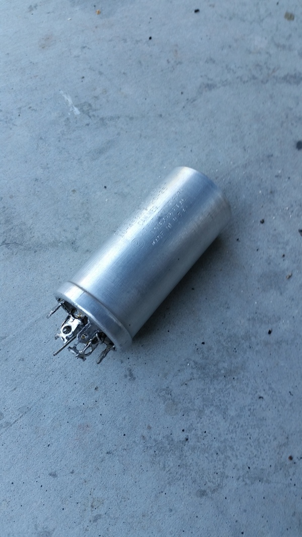
Good progress today. The last of the band switch wiring is complete, and the filter can is restuffed - pics to follow soon.
I had not tried reworking one of the cans before - this was the first time I have been faced with the challenge. Desoldering and removing it from the chassis took a little while. at this point, quite a bit of corrosion was evident where the negative/common tab crimps in the end of the can. The rolled edge was lifted as carefully as I could with a modified blade, and with a little heat from the heat gun and pulling gingerly on the tabs, the innards were revealed. Some juggling established a good configuration for the new capacitors and they were soldered in - leads running through discretely drilled holes next to the + terminals so that they could be soldered. Then came the process to replace the parts and re-close the can. This is the part that gave most concern, but with slow careful working, I was very happy with the final result.
One point to note, I had to file the shoulders of the twist tabs in order to get the can to seat against the chassis. I think this is down to the difference in roll profile of the can's edge after it was reassembled.
All in all, I am happy with the results. 
I don't hold with furniture that talks.
Posts: 4,707
Threads: 51
Joined: Sep 2008
City: Sandwick, BC, CA
You are lucky Ed, on the A-30 I'm working on the can was a four section unit, 10 uf, 10 uf, 10 uf at 450 vdc, and a 20 uf at 25 vdc. I'm not sure whether I would have been able to restuff the thing even if I wanted to, it's only about 2'' high, and 1-1/4 in diameter at most, so I installed a terminal strip to make replacement by a future owner easier. The RCA A-20, A-22, and A-23s are even worse, they are a three section can, 10 uf, 10 uf at 450 vdc, and a 20 uf at 25 vdc, and the can is 2'' tall and maybe 3/4'' across, I don't think I could restuff one of those, but maybe. You can see after taking your can apart that the innards are made like a jelly roll, the negative foil runs all the way through and is used for all of the sections, so they can make it more compact then using even the skinniest radial lead caps, like the pencil style Nichicons.
Anyhow I stopped working on the A-30 for the time being, I have more resistors to hunt down, as well as a replacement cathode cap, but I haven't had the time. Just after you finished working under your car, I started crawling around under a mobile home with a jack and stacks of wood cribbing, the floor was so unlevel it was getting scary.
Regards
Arran
Posts: 1,288
Threads: 44
Joined: Nov 2017
City: Menlo Park
State, Province, Country: CA
As removed from the radio
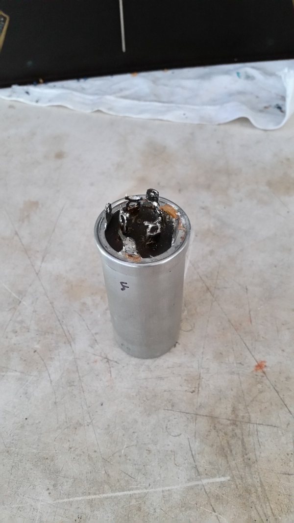
Peeled, and the twist lock ring removed - you can see the corrosion resulting from leakage.
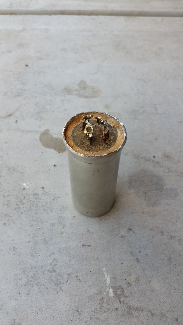
Here's what is inside - rather dry....:
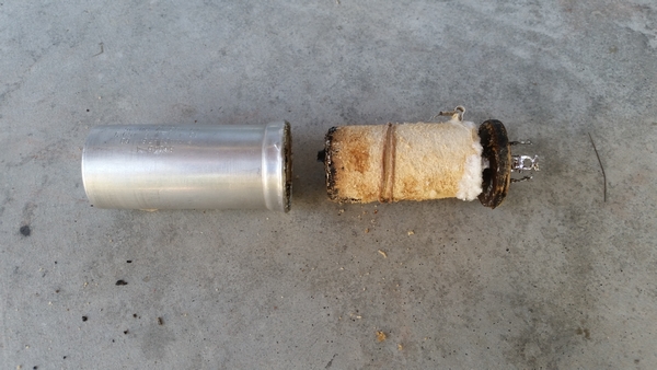
Multi-story capacitors..:
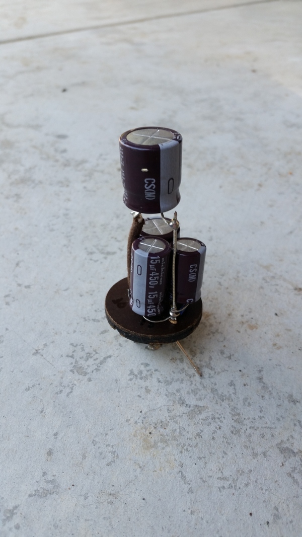
All back together:
I don't hold with furniture that talks.
Posts: 4,382
Threads: 412
Joined: Jun 2011
City: Boston
State, Province, Country: Massachusetts
A very neat job on that part Ed.
paul
Tubetalk1
Posts: 1,288
Threads: 44
Joined: Nov 2017
City: Menlo Park
State, Province, Country: CA
After moving a ton of blocks and building a retaining wall, I decided it was radio time again. Today, starting to look at the smaller component recap, and that took me to the cluster around the tone switch. I started to replace what I saw, then had cause to refer to the schematic. Oh deary me, none of this looks like what I'm working on..
Things changed from a happy-go-lucky soldering session to a sketch, trace and play detective. Our arch-enemy had been at work, clipping out some caps entirely and putting in entirely different values for others. I think now I have discerned how this was put together originally, and how the parts were arranged.
I probed around some of the resistors while I was checking things over. Many are far out of tolerance, including a few crucial ones in the signal path.
I mentioned before that the friend who gave us this set asked me, many years ago, to see if I could help improve its reception. Given the poor state of parts, and the mixed up efforts at repair/restoration it is not surprising that he wasn't satisfied.
Next session, in a couple of weeks, I'll sort out the tone circuit, and continue the work to recap and replace resistors.
Cheers
Ed
I don't hold with furniture that talks.
Users browsing this thread: 3 Guest(s)
|
|
Recent Posts
|
|
Philco 60 Squealing
|
| Usually a wave trap is for keeping IF signals from entering the antenna and from leaving the antenna. You feed an IF sig...RodB — 09:30 PM |
|
Philco 60 Squealing
|
|
I just peaked it for the best signal at 600.
NULL it for IF frequency, originally it would have been null for 500kh...Chas — 08:05 PM |
|
Philco 60 Squealing
|
| Wavetrap no longer matters.morzh — 05:19 PM |
|
Philco 60 Squealing
|
| Rod, I had checked out your suggestions but did not help. I did solder the ground rivets to the chassis as Chas suggeste...dconant — 04:52 PM |
|
37-690 Bass Choke Replacement
|
| Yeah, I know, Mouser and Digikey don't have "big iron" components. For some reason Philco was messing with the...Radiodial — 04:25 PM |
|
37-690 Bass Choke Replacement
|
| Yes, I just had to deal with that while repairing the 37-604 Philco. Exactly that value choke was gone. And the current ...morzh — 03:52 PM |
|
37-690 Bass Choke Replacement
|
| Ah, now where to find one.
I've into this before on smaller sets, I now recall. Hammond makes one that is only rated...Radiodial — 03:27 PM |
|
Philco 38-7 Speaker
|
| Ask the admins to put them together.
As for the renaming, while inside the thread, you simply press "New reply&quo...morzh — 02:23 PM |
|
37-690 Bass Choke Replacement
|
|
This is the parts catalog.
32-7528 choke is 65H, 10mA, 2,250 Ohm inductance.
Find a suitable one.morzh — 02:18 PM |
|
37-690 Bass Choke Replacement
|
| While troubleshooting the no bass amplification issue, I think I found the culprit. The choke #104 is reading 164K ohms....Radiodial — 01:42 PM |
|
Who's Online
|
There are currently 3840 online users. [Complete List]
» 1 Member(s) | 3839 Guest(s)
|
|
|

|
 
|


![[-] [-]](https://philcoradio.com/phorum/images/bootbb/collapse.png)


