Welcome Guest! Be sure you know and follow the Phorum Rules before posting. Thank you and Enjoy! (January 12) x

Thread Closed
Thread Rating:
  • 0 Vote(s) - 0 Average
  • 1
  • 2
  • 3
  • 4
  • 5

Protection jig for SS generator
#1

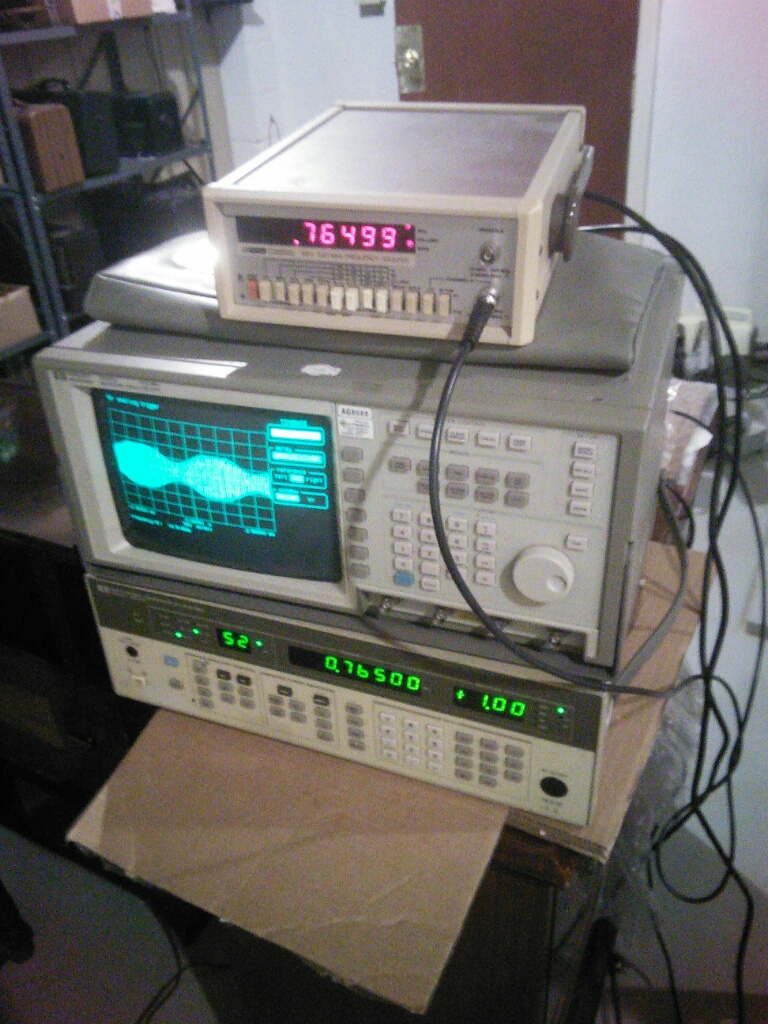
As I told before, I bought an HP sig gen. Before I use it, I decided to make a quick jig to protect it from those charges that sonetimes kill SS output, even when connected through a cap.

This is the generator (the bottom piece)
   

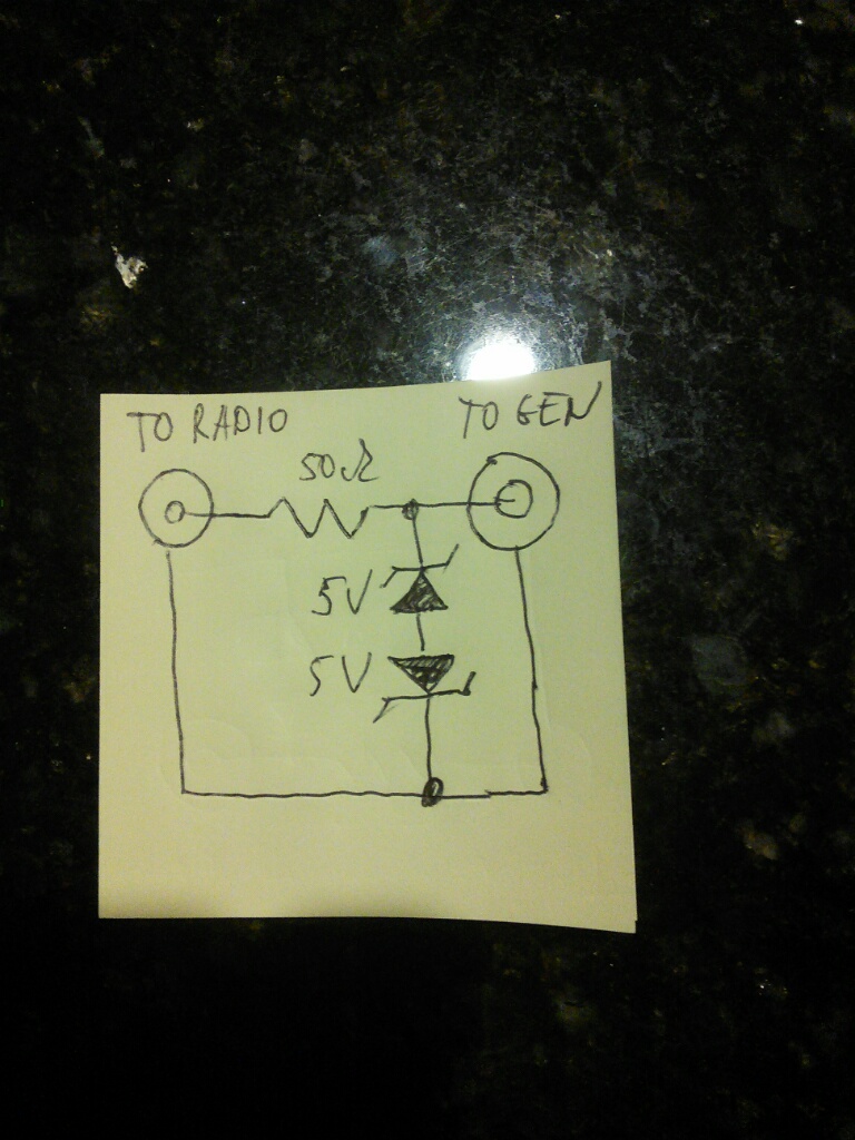
This is the sch of the jig

The resistor is small, can be from ohms to 20-50 ohm. The Zener is one part, back to back pair. The polarity doesn't matter, could be plusses or minuses out.  I had 5.6V ones.
The voltage is thus clamped at 5.6+0.7V=6.3V. Could be higher or lower. The output signal is 1V RMS or 1.4VPP so anything between 2V and 10V is ok.
   

This is the jig
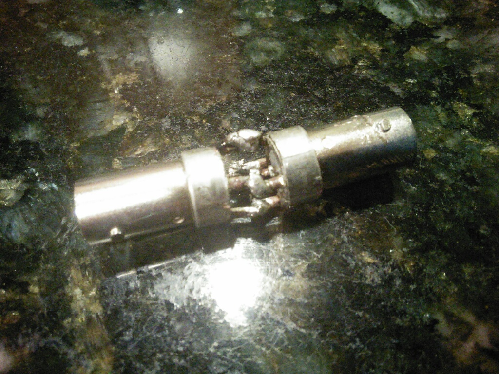


The zener and the resistor are small, SC-89-3 and 0603 respectively. But the connectors soldered back to back are so rigid that no effort is transferred to the small components inside.

People who do not drink, do not smoke, do not eat red meat will one day feel really stupid lying there and dying from nothing.
#2

Very neat Mike!

I don't hold with furniture that talks.
#3

Just bumping this up since Ron's Signal Generator thread was resurrected.

Thanks Mike!

John KK4ZLF
Lexington, KY
"illegitimis non carborundum"
#4

Yeah...imagine me soldering this with my shaky hands.....

I actually amazed myself this week, I designed a board that has to use very small components, the board itself (have to hold it in hands, no holder) - 0.5x1.8", and the components like SC-70-8, with pins 0.5mm (20 mils) from each other with the pin itself being 12 mils wide, with 8 mils space between them. Compared to that the 0402 resistors (40x20 mils) are gigantic.

Soldered the whole thing.

People who do not drink, do not smoke, do not eat red meat will one day feel really stupid lying there and dying from nothing.


Users browsing this thread: 1 Guest(s)
[-]
Recent Posts
Refinishing Ideas
Thanks. I will look into. Billpoulsbobill — 11:23 AM
My Philco 37-116 Restore
Why do the flood lights have 2 wires running to the shell of each light when the inner conductor only has one to each? ...dconant — 10:54 AM
Philco 46-480 Electronic Restoration
OOPS!! if there is a "flag" running up the side of the tube that touches the shield, then yes, a shield belon...MrFixr55 — 10:03 AM
Philco 46-480 Electronic Restoration
Thanks for pointing out that shield! I will try to find out where else it may belong. I simply installed it back where i...jrblasde — 10:02 AM
Philco 46-480 Electronic Restoration
Very nice job. A real contrast between how easy the main chassis is to work on, vs how tightly the RF chassis is packed...MrFixr55 — 09:31 AM
Philco 46-480 Electronic Restoration
After sleeping on it, I believe the issue is that I may have forgotten to install a ground connection between the RF cha...jrblasde — 09:21 AM
Refinishing Ideas
Hi Poulsbobl, I think that you could get away with it.  In the Philco Library, there is a parts listand specs for sp...MrFixr55 — 11:54 PM
Philco 46-480 Electronic Restoration
The sleeving for the transformer arrived early, so I went ahead and finished reassembling. The chassis looks far better ...jrblasde — 10:15 PM
Philco 610B oscillator wiring
I don't know what you are referring to when you say "tube cathode ground". Ground is a connection to the chass...RodB — 05:56 PM
Zenith H725
Good points, Arran. I haven't encountered this problem with any other radio (all earlier vintages), so am learning here....EdHolland — 05:32 PM

[-]
Who's Online
There are currently no members online.

>