Posts: 365
Threads: 76
Joined: Oct 2014
City: Winter Haven, FL
Recapped, changed resistors, replaced wiring, and aligned. It working great. Put it back in the cabinet, powered on, and after the tubes warmed up, got a hum. Removed chassis, and still have a hum. I can still pick up stations. Hum does not change with the volume. Rechecked the wiring, paralled new filter caps, no change. When I prod around the 42 output tube, hum volume seems to vary. Stuck another 42 in there, same as first one.
Since it worked before I put it in the cabinet, I focused my attention on solder joints and wiring. Nothing wrong there. And since the hum doesn't change with the volume, I thought it might be easier to find. But the volume pot is on the antenna lead-in.
Any ideas?
Thanks,
Pat
Posts: 11
Threads: 5
Joined: Oct 2018
City: Burlington
State, Province, Country: Wisc
Hello Pat,
I am currently restoring a 40-200 and performed everything you did, caps, resistors... Worked well for a day or two and started getting a hum. Caps are all good. It ended up being the phase inverter tube socket. I cleaned the socket using 90% alcohol and welder's tip cleaning brush. Plugged in the tube and bingo, no more hum.
On another radio I restored the problem was a solder joint on a tube pin. I re-soldered it by placing the tube upright, heating the pin and letting the solder get sucked up into the pin.
You may also want to check all of your solder joints. I use a chopstick to poke around under the chassis.
Denis R.
(This post was last modified: 11-24-2018, 10:58 AM by
drrenaud.)
Posts: 751
Threads: 91
Joined: Nov 2015
City: Jonesboro
State, Province, Country: AR
Try checking the rivets to the tube shield bases, make sure the tube shield is making good contact with the base, and the base has good contact with the chassis.
Also, I have a 45C I worked on some time ago, and it had a loud hum 1st time I powered it up. It turned out the common wire to the electrolytic filter caps on the ground side had a break in it. It was a solid wire, and the break was inside the insulation, so it wasn't visible.
As soon as I replaced it with a new wire, I was up and running.

Blessings,
Jeff W.
Jonesboro, Arkansas
http://jeffsradios.weebly.com
God loves you as you are, not as you should be, because none of us are as we should be. - Brennan Manning
Posts: 7,301
Threads: 269
Joined: Dec 2009
City: Roslyn Pa
I had an 84 a while back w/that problem and ended up being a bad rivet connection on the 42 socket.
YMMV
When my pals were reading comic books
I was down in the basement in my dad's
workshop. Perusing his Sam's Photofoacts
Vol 1-50 admiring the old set and trying to
figure out what all those squiggly meant.
Circa 1966
Now I think I've got!
Terry
Posts: 365
Threads: 76
Joined: Oct 2014
City: Winter Haven, FL
All good tips. Thanks. I'll go see what I can find.
Posts: 365
Threads: 76
Joined: Oct 2014
City: Winter Haven, FL
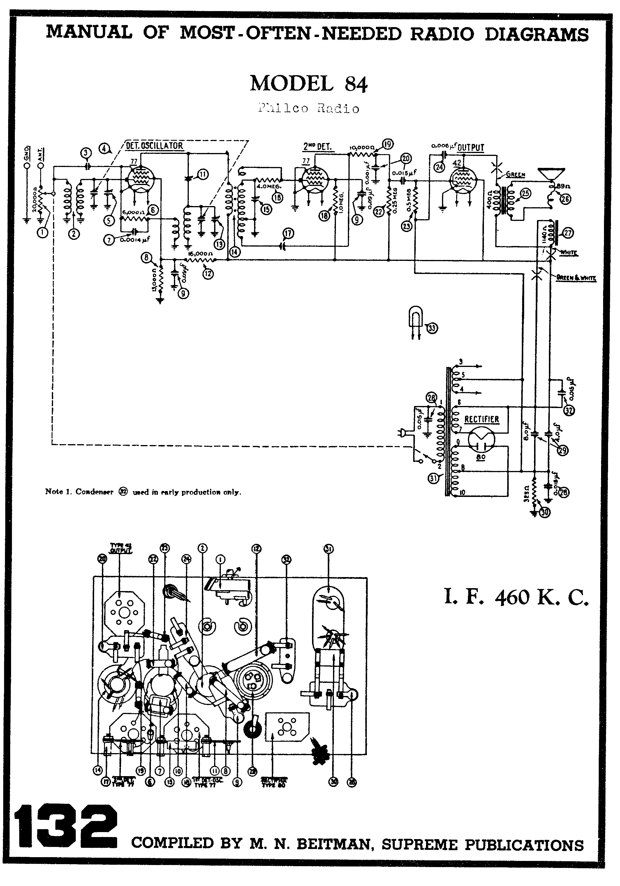
Well....Checked all solder joints, cleaned all tube sockets, by-passed almost all wires with a jumper, one at a time. I found one loose wire, resoldered it, but the only change was prodding the entire chassis now has no effect at all. Thought I'd post the schematic. Maybe there is an error in it somewhere.
[Image:
https://i1367.photobucket.com/albums/r79...nbvfhn.jpg]
Posts: 1,262
Threads: 32
Joined: Jan 2014
City: Wellborn Florida

Maybe this will help Beitmans has the parts layout under the hood.
Posts: 285
Threads: 18
Joined: Nov 2016
City: Cromwell
State, Province, Country: CT
I repaired on of these with the same hum. It was the rivets to 77 tube shield base. I drilled them out and used 4-40 screws with star washers and nuts to replace the rivets. No more hum. The 77 tube being a detector and 1st audio tube makes it susceptible to hum. Plus the audio runs full tilt to the 42 as there is no audio volume control.
Tony
“People may not remember how fast you did a job, but they will remember how well you did it”


![[-] [-]](https://philcoradio.com/phorum/images/bootbb/collapse.png)


