Posts: 1,204
Threads: 84
Joined: Jan 2014
City: Annapolis, IL
State, Province, Country: USA
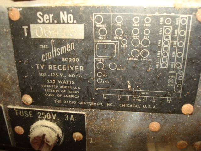
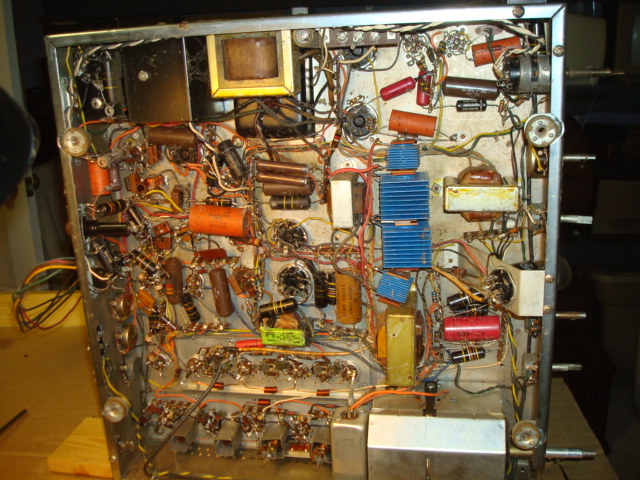
Here is the selected project, the Craftsmen. I need to check to see if I have the Sams on it. Looks like the correct tubes in the correct sockets exc a 6SL7 in place of a 6SN7 vertical osc. From the looks of the dust, nothing has been disturbed. Under chassis about the only thing I see that has been worked on is the power switch and rectifiers. The rest looks original. Lots of "bee's" underneath. I can see a couple of the electrolytics have leaked a little. Good thing is that it looks like I can get to about everything pretty easy for a recap. Picture tube checked good, gun looks shiny.
I did a few quick checks. The cord was deteriorated so bad I doubt it was even plugged in in the last 30 years. The fuse checked ok and get 2-3 ohms at the cord plug with the switch on. I don't see any obvious signs of a power transformer meltdown. The flyback looks to be in good shape as everything else in the HV box. This was a "junk store" find, way back in a corner, $10. Figured it was worth that for parts, esp if the big tube was good. Sadly, the cabinet got sold and the knobs were no where to be found. I am sure was 'repurposed', probably a dumb aquarium. They said it was a beauty. A day late and a dollar short. Well, at least I was able to save the chassis. It would only have been a matter of time until the neck got knocked off the tube. So, here begins the project. If I wreck it, it's just a chassis. If it lives, then it would be a pretty interesting piece of history.


If I could find the place called "Somewhere", I could find "Anything" 
Tim
Jesus cried out and said, "Whoever believes in me , believes not in me but in him who sent me" John 12:44
Posts: 4,429
Threads: 418
Joined: Jun 2011
City: Boston
State, Province, Country: Massachusetts
Never seen so many Selenium Rectifiers in one set!
PAul
Tubetalk1
Posts: 4,859
Threads: 54
Joined: Sep 2008
City: Sandwick, BC, CA
I seem to remember seeing Radio-Craftsman ads in many post war electronics magazines such as Radio-Electronics, I believe that they were like Meisner where the majority of what they sold were aftermarket chassis without cabinets. So the cabinet that this chassis sat in was either custom built or an aftermarket one.
Anyhow the power supply is rather novel, it would appear to employ selenium rectifiers rather then using tubes such as a 5U4, as there is none shown on the tube diagram, and a power transformer as well. Most sets that I have seen with selenium rectifiers are series string, no power transformer, and use a pair of them as voltage doublers.
Regards
Arran
Posts: 1,204
Threads: 84
Joined: Jan 2014
City: Annapolis, IL
State, Province, Country: USA
I did some checks last night now that I have the schematic. I checked from B+ to chassis and no shorts. Found a 20a fuse in the 3a holder - not good. I disconnected the power transformer HV from the chassis, checked again for shorts. Then stuck a dim bulb tester and amp meter in the AC line, then did a slow power up via the variac. So far so good. Current stayed around .5 amp or so and the bulb was very dim. All the tubes lit, next I checked the output from the PT. I was at 216 ac across and 107, 106 to center tap. That was at 120v on the line. Looks like the transformer has hopes. Next, (don't shoot me!) I reconnected the PT leads and did a slow power up to about 50v, then again to about 70v while monitoring the B+ and current. I also had the scope on the H output grid. Current stayed near .7a, and the DC was sitting around 107 off L1, and 50 off L2. These are the 2 main B+ sources. I let it sit for a few minutes and powered off. To the touch I had a 400v cap under chassis barely warm and one of the cans. So I know there is some leakage. I didn't observe anything starting up like the H-osc, vertical or sound. I did note that it has had some vertical circuit work done, about all of it. Looks like an osc transformer, soldering around the sync amp and possibly a vertical output transformer. Typical. What is it about the vertical section that is always so troublesome? Even into the more modern sets. Oh well, more later.
If I could find the place called "Somewhere", I could find "Anything" 
Tim
Jesus cried out and said, "Whoever believes in me , believes not in me but in him who sent me" John 12:44
Posts: 1,204
Threads: 84
Joined: Jan 2014
City: Annapolis, IL
State, Province, Country: USA
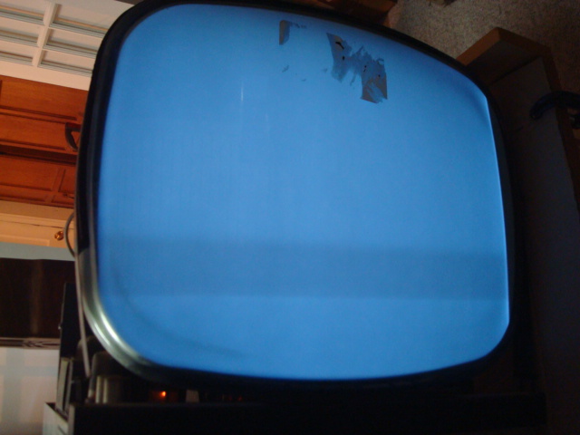
I did a slow power up without the bulb in the circuit. It was dropping the current enough that nothing would work. I monitored the current and it was in the 1.5 amp range. I could get some static in the sound, hear the vertical running and the horizontal, but it seemed a little upset over something and I only had about 2kv on the high voltage. I did some checks around the horizontal and damper and found the voltages close enough. So I did a test on the HV tube and found it dead. I found one in a junk box and it at least moved the meter on the tube tester so I put it in and this is what I got:
 I have about 14kv on the meter now. No video or sound. Flashes when I change channels. I think this is a split carrier set, so I'm betting something in the tuner. Typical vertical sweep issues. That's as far as I got.
If I could find the place called "Somewhere", I could find "Anything" 
Tim
Jesus cried out and said, "Whoever believes in me , believes not in me but in him who sent me" John 12:44
Posts: 1,204
Threads: 84
Joined: Jan 2014
City: Annapolis, IL
State, Province, Country: USA
I recapped the vertical section and found one cracked. Now I have full vertical sweep. My B+ is still a little low. I haven't gotten to the power supply recap or rectifiers yet. I did the horizontal and video sections, but didn't get any change. Still no video/sound. So, I need to get more caps ordered.


If I could find the place called "Somewhere", I could find "Anything" 
Tim
Jesus cried out and said, "Whoever believes in me , believes not in me but in him who sent me" John 12:44
Posts: 1,204
Threads: 84
Joined: Jan 2014
City: Annapolis, IL
State, Province, Country: USA
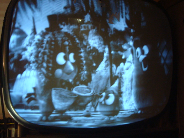
I have made "some" progress. I am in an area where things are not listed in the schematic. It looks like these TV's had had some changes that aren't documented very well. The vertical section has been upgraded and follows the RC201. The rest is kind of a mix, so I have to follow 2 schematics, which of course, component ID numbers are all different. I changed a big electrolytic and small paper cap and the B+ came up some. I still don't have any video or sound from the antenna input, so as a test, I injected a video signal into the 1st video amp 6AU6. I was able to lock the vertical, but the horizontal was a little more difficult. I did manage by turning up the "drive" , but the hold control is at the extreme end of travel. Here is what I got:


I wouldn't be surprised if this is the 1st picture that has been on this screen in over 50 years! 
If I could find the place called "Somewhere", I could find "Anything" 
Tim
Jesus cried out and said, "Whoever believes in me , believes not in me but in him who sent me" John 12:44
Posts: 1,475
Threads: 69
Joined: Nov 2012
City: Kansas city, MO.
Looks like your making progress. I don't know a thing about the old tube televisions or the new ones for that matter, but find the old ones interesting. Good luck Tim.
Posts: 1,204
Threads: 84
Joined: Jan 2014
City: Annapolis, IL
State, Province, Country: USA
If I could find the place called "Somewhere", I could find "Anything" 
Tim
Jesus cried out and said, "Whoever believes in me , believes not in me but in him who sent me" John 12:44
(This post was last modified: 02-13-2019, 01:57 PM by TV MAN.
Edit Reason: correct error on tube number
)
Posts: 4,859
Threads: 54
Joined: Sep 2008
City: Sandwick, BC, CA
You did mention recapping certain sections of the set, but don't forget about the resistors as well, sometimes they read fine when cold but change value when you apply voltage across them.
Regards
Arran
Posts: 1,204
Threads: 84
Joined: Jan 2014
City: Annapolis, IL
State, Province, Country: USA
You do have a point. I have been checking them but I think I should replace in the critical circuits, like the sync separator, agc and oscillators. What's bad about this set is the circuit upgrades and mods that aren't documented in the service information. Some of the colors are really hard to read on those old resistors. One cap I did overlook is the high voltage filter cap. I have heard those can cause some really strange problems.
If I could find the place called "Somewhere", I could find "Anything" 
Tim
Jesus cried out and said, "Whoever believes in me , believes not in me but in him who sent me" John 12:44
Posts: 1,204
Threads: 84
Joined: Jan 2014
City: Annapolis, IL
State, Province, Country: USA
I kinda went silent on this thread due to work and other projects. Got the E-caps out and ready to re-stuff, but thats as far as I have gotten. It is collecting dust on my bench and probably will until cold weather/fall hits. Most of my work is seasonal and outdoors, and pretty much owns me until its over for the season. So, several projects are on hold, but not forgotten, including this one.
If I could find the place called "Somewhere", I could find "Anything" 
Tim
Jesus cried out and said, "Whoever believes in me , believes not in me but in him who sent me" John 12:44
Posts: 1,204
Threads: 84
Joined: Jan 2014
City: Annapolis, IL
State, Province, Country: USA
It's been some time, but I have finally felt like getting back into the radio room and have been working on this TV some more. I got the E caps restuffed and back in. I'm looking at the old rectifiers now. I should replace those with some diodes. Any thoughts of dropping resistor(s) or just solder in some good heavy diodes? I'm open to suggestions on this. I'd like to get that done, then gonna power up and see where I am before moving on to the next section. I have a heavy bridge, but don't know if that will work either.
If I could find the place called "Somewhere", I could find "Anything" 
Tim
Jesus cried out and said, "Whoever believes in me , believes not in me but in him who sent me" John 12:44
Posts: 1,204
Threads: 84
Joined: Jan 2014
City: Annapolis, IL
State, Province, Country: USA
I got the rectifiers replaced. I just stick a bridge in there and it works. The B+ came up quite a bit but it I still have sync issues. Both horizontal and vertical. Pic is very weak unless I inject a video signal into the 1st amp, even with a good signal, the sync is still out of whack. Im concentrating on the sync separator/agc area. They have a 6BF6 in place of a 6C4. The socket was rewired, so I'm wondering of this could be contributing. I replaced it with a 6AQ6 with no change. I'm going after the micas and resistors in this area. Voltages are off as well.
I replaced the 5J6 with a NOS 6J6a in the tuner, which is the correct tube. I lost both sound and video. I swapped it back and I got my sound back, but the video is weaker and comes and goes. Sounding like a tuner problem. Who knows. May be the agc gone cuckoo.

If I could find the place called "Somewhere", I could find "Anything" 
Tim
Jesus cried out and said, "Whoever believes in me , believes not in me but in him who sent me" John 12:44
Posts: 1,204
Threads: 84
Joined: Jan 2014
City: Annapolis, IL
State, Province, Country: USA
Finally got back into this set. I recapped and replaced some out of tollerace resistors in the sync separator, powered up and had no video at all! Did some checks and found 0 plate volts on the video output tube and a very hot plate load resistor. Found a short to ground - seems one of the peaking coils got against a ground pin on the terminal strip and shorted! Moved that away and got my video back. Nothing from the tuner still, get something from injection. Sync issues still a problem. Gonna have to dig deeper. Kinda starting to suspect it may be something to do with DC restoration on the video. Sync takeoff is between 1st video amp and output. May have to get my scope working and look at things.
If I could find the place called "Somewhere", I could find "Anything" 
Tim
Jesus cried out and said, "Whoever believes in me , believes not in me but in him who sent me" John 12:44
Users browsing this thread: 1 Guest(s)
|
|
Recent Posts
|
|
Zenith H725
|
| The PSU filter cap arrived today (thank you USPS!) so I will work on that later.
Meanwhile, I have the dial, speaker...EdHolland — 06:42 PM |
|
Philco 610B oscillator wiring
|
| Thanks Terry. After checking my notes I think I recorded about -10v at the 6A7 G4/control grid. The screen grid (G3 &...Tubester — 05:59 PM |
|
The list of my radio & TV collection!
|
| Magical chords of forgotten melodies, old nostalgic music on an old radio... Saturday night blues on the Mid-Waves on an...RadioSvit — 12:20 PM |
|
Philco 42-345 Restoration/Repair
|
| Thank you MrFixr55 the issue with this radio is that the internal coil antenna is missing and there was a wire in its pl...osanders0311 — 11:34 AM |
|
Philco 610B oscillator wiring
|
| Regarding the oscillator circuit which is comprised of the 6A7's cathode, control grid, and screen grid. These elements ...Radioroslyn — 10:33 AM |
|
Philco 42-345 Restoration/Repair
|
| Hi OSanders,
First off, welcome to the Philco Phorum where Phine Phamily-Phriendly Pholks Phull of Philco Phacts and P...MrFixr55 — 08:41 AM |
|
Philco 42-345 Restoration/Repair
|
| Today I've been reading through the site trying to learn more about this radio. I also soldered the lose power cord cabl...osanders0311 — 08:24 PM |
|
Philco 610B oscillator wiring
|
| Thanks David! I do have that same later prodution model 610 schematic. I've also studied the Philco service bulletins fo...Tubester — 08:12 PM |
|
Philco 610B oscillator wiring
|
| Some info from Beitmans says late production. David David — 06:06 PM |
|
Restoring Philco 96
|
| Oh wow! Just found this thread. Brings me back to early days on this phorum. I did a 96 back in 2017. Thread here:
...rfeenstra — 06:05 PM |
|
Who's Online
|
There are currently 3076 online users. [Complete List]
» 1 Member(s) | 3075 Guest(s)
|
|
|

|
 
|


![[-] [-]](https://philcoradio.com/phorum/images/bootbb/collapse.png)


