Posts: 1,199
Threads: 49
Joined: Oct 2017
City: Allendale, MI
Posts: 1,199
Threads: 49
Joined: Oct 2017
City: Allendale, MI
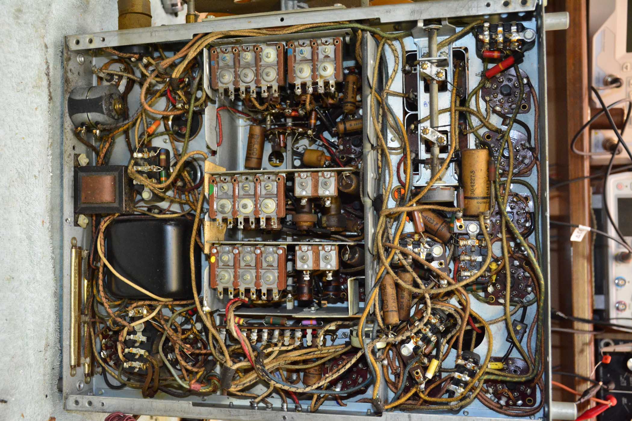
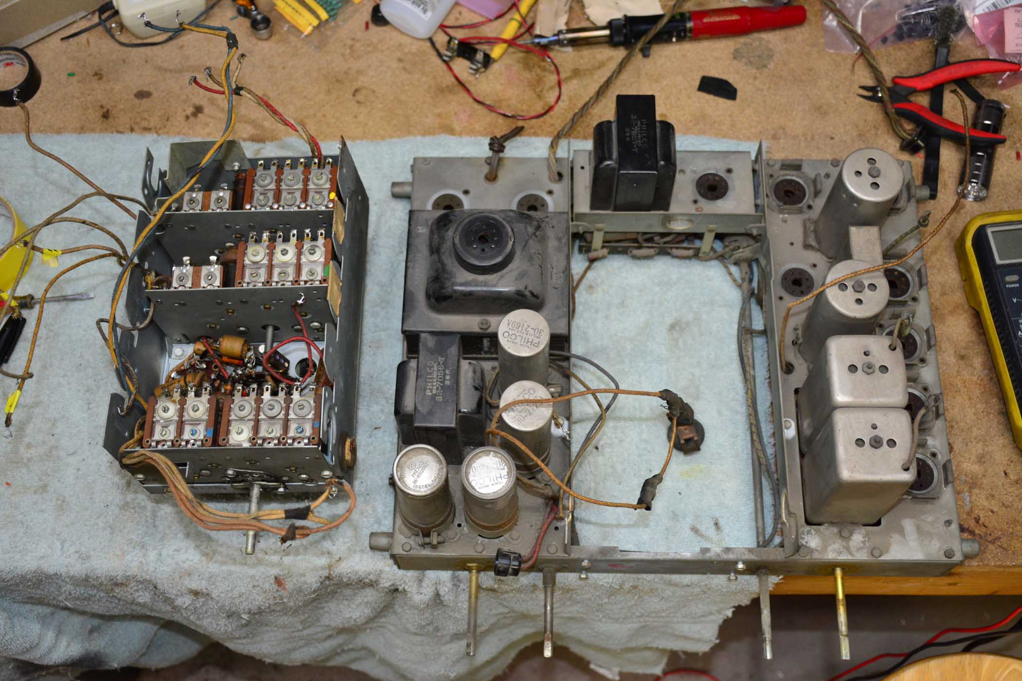
To get at all of the caps, I had to remove 2 of the switch/coil sections. There is a capacitor buried between wafers and is easily accessible by taking things apart.
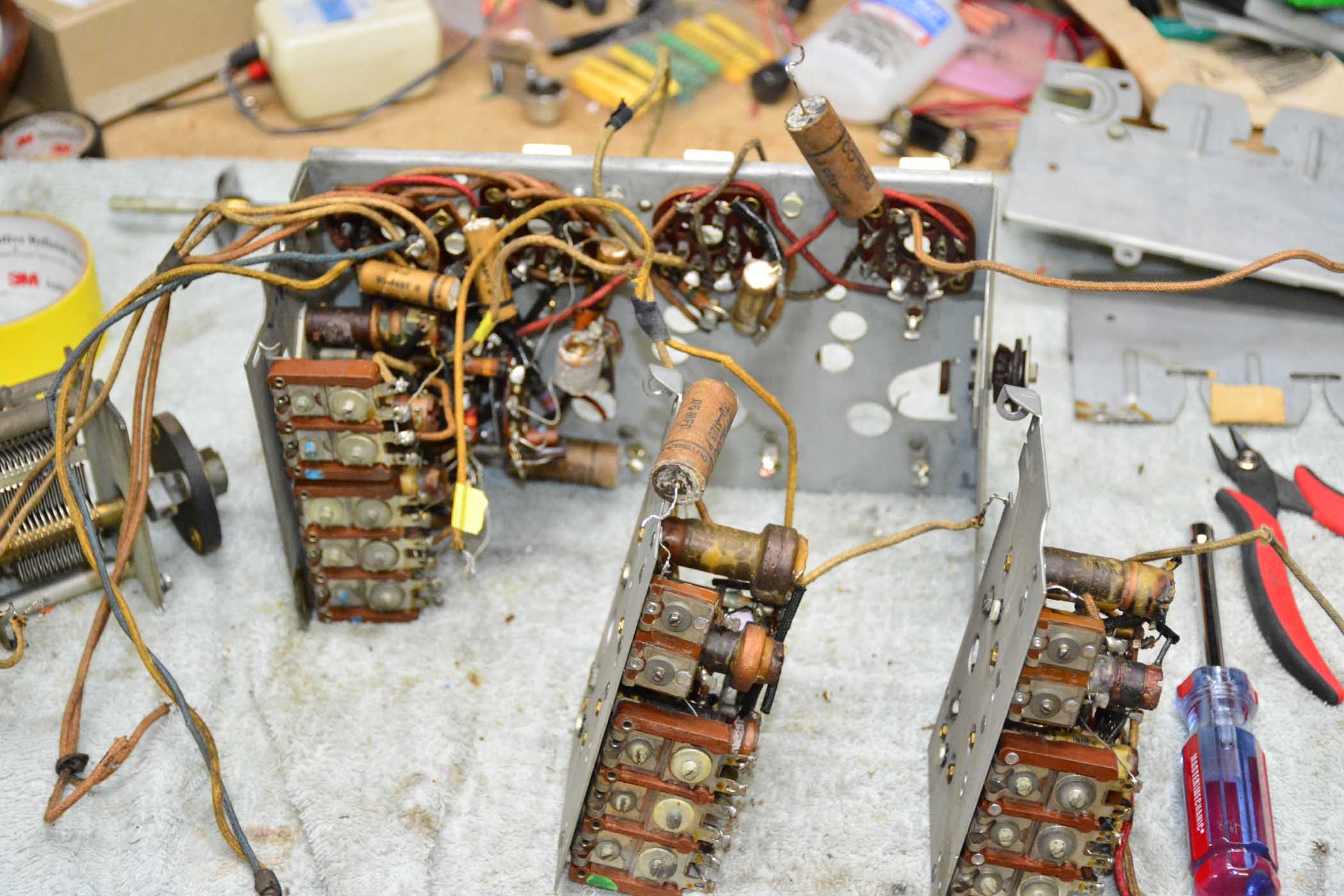
Capacitors stuffed with new and resistors checked. I should have taken a pic of the buried capacitors, but i didn't.
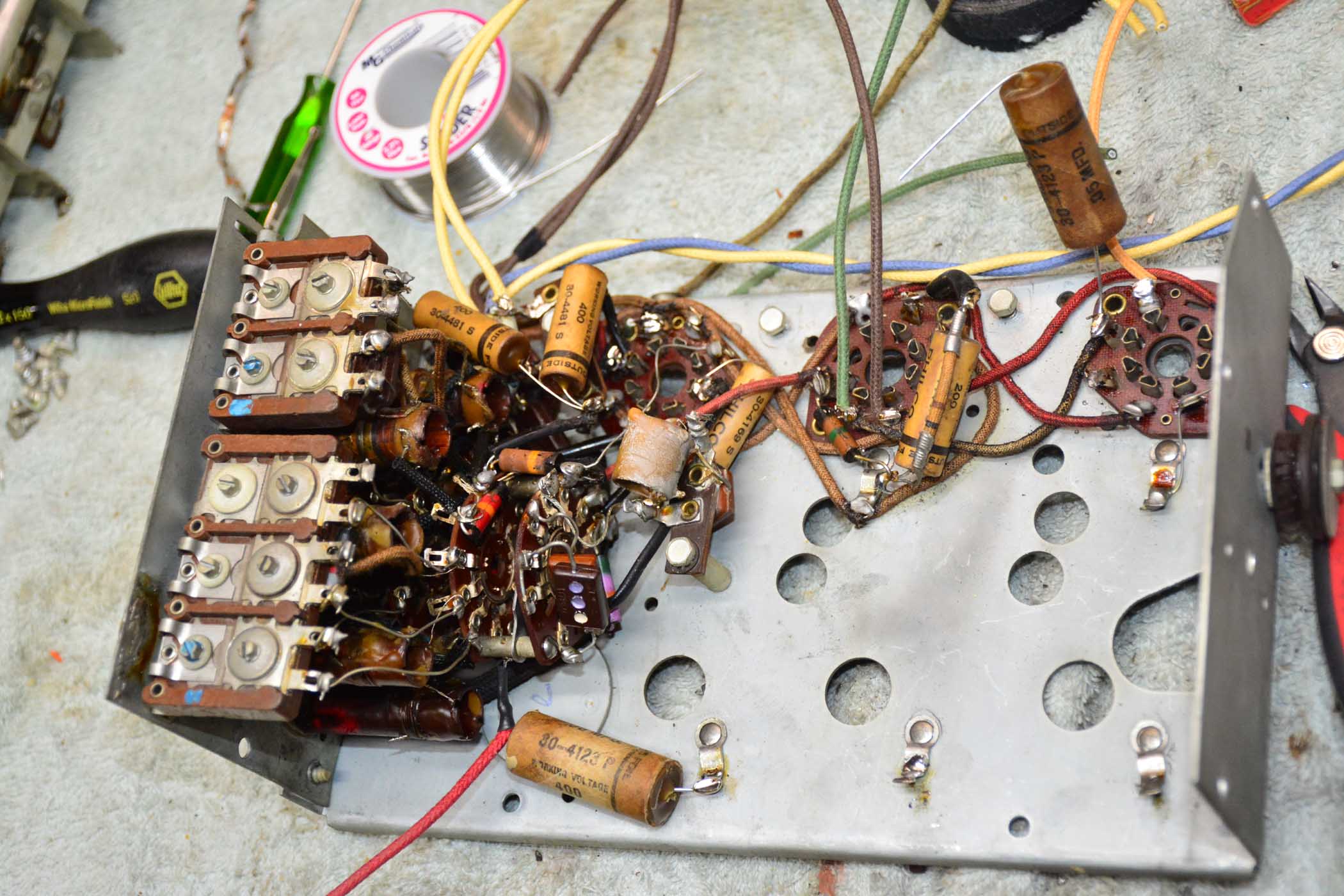
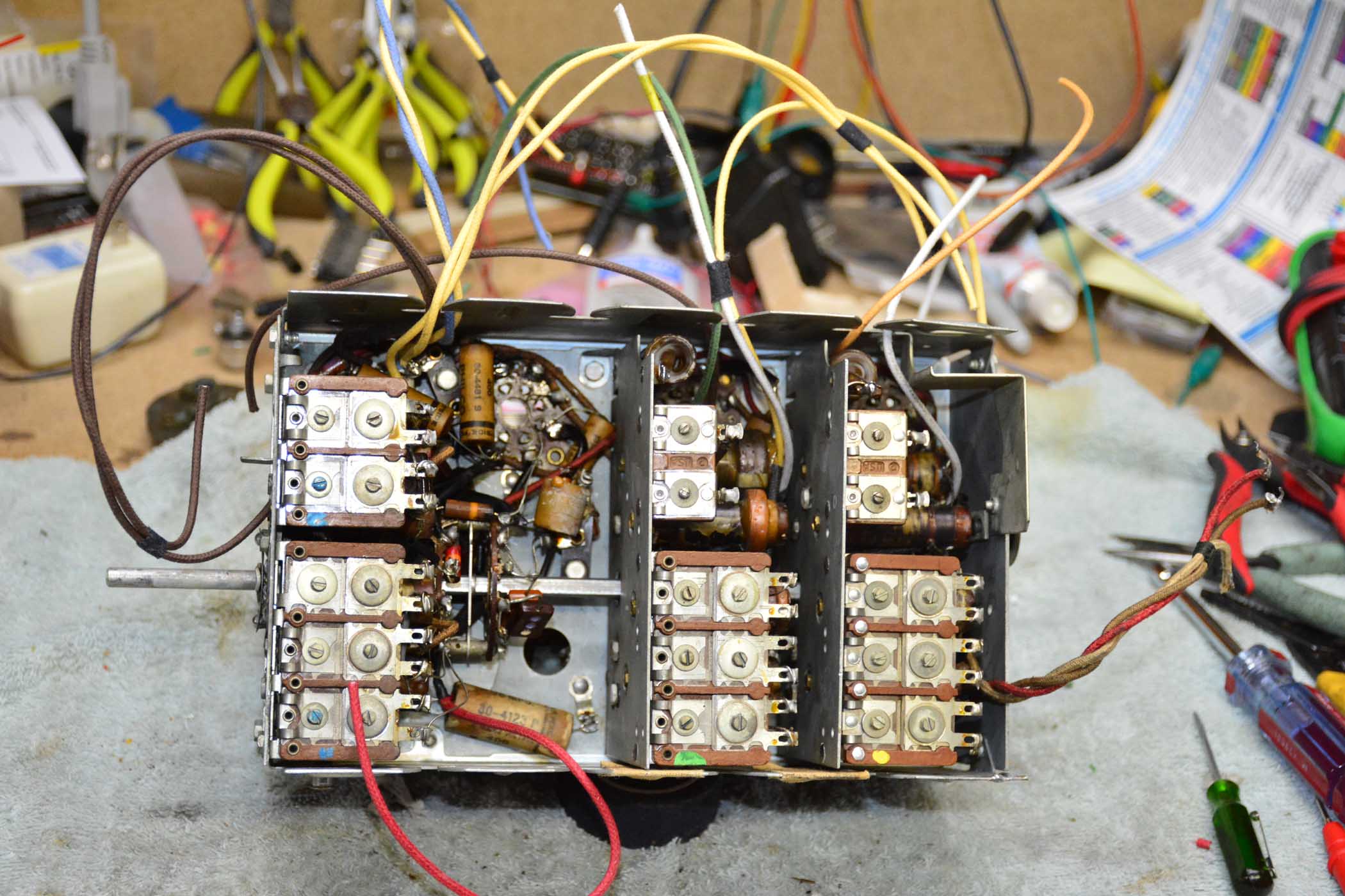
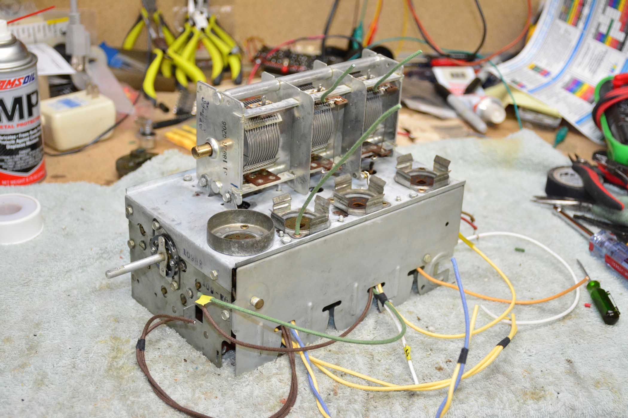
Sub-chassis reassembled. Most of the sub-chassis connection wires were brittle and so replaced. Only the antenna wires and connection wires on the chassis remain original. The antenna wires, for some reason, were quire flexible and obviously do not carry a high tension signal.
Posts: 1,889
Threads: 214
Joined: May 2015
City: Seattle
State, Province, Country: WA
 very exciting!
Posts: 1,199
Threads: 49
Joined: Oct 2017
City: Allendale, MI
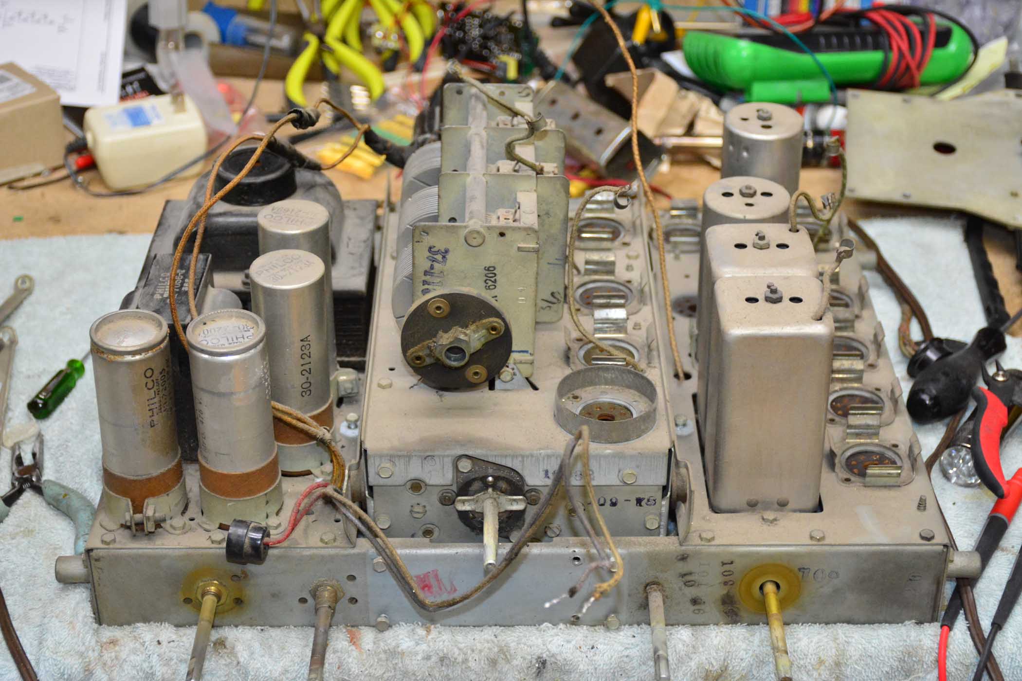
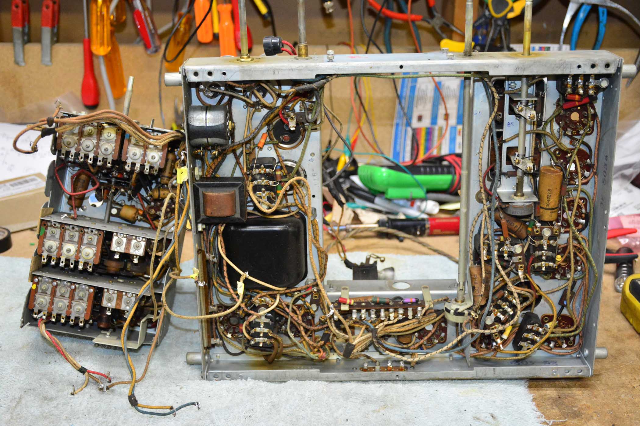
Need some advice! I set the sub-chassis aside and started examining the main chassis. Most of the wires are "crispy". Any movement and you can hear and feel the rubber inside the cloth break apart. This concerns me on the high voltage lines. Even the wires that come out of the PT are very ridged and will crack with the slightest movement. I'm thinking of a a complete re-wire including the leads coming from the PT. It's hard to determine the wire colors and , of course, a lot of the wires with tracers are unobtainium, and there are a lot of them. I would like to keep it looking original but would really feel better replacing the wires. What do you guys do in this situation? Nathan, I noticed you kept most of the original wire. Were your's in good shape or am I over reacting to the possibility of leakage, especially on the B+ lines? Russ, I know you've seen corona discharge on high tension lines. What is your solution?
Thanks in advance!!!
Posts: 1,889
Threads: 214
Joined: May 2015
City: Seattle
State, Province, Country: WA
The state of cloth covered wire varies. On the 38-116 it was still pretty pliable so I left it alone. Even it's stiff I usually only replace cloth wire that has cracked or been damaged. To me stiff cloth wire that is intact isn't a problem (unlike rubber wire that is flaking of insulation).
On a 37-650 I worked on the cloth wire was in worse shape so I did replace the wires that had to be moved (e.g. going to RF sub chassis).
In replacing wires there's not only the difficulty of obtaining original looking wires but also the concern for keeping wire placement / routing the same.
Posts: 1,199
Threads: 49
Joined: Oct 2017
City: Allendale, MI
I'm afraid I'm going to damage much of the wire by removing the bakelite and electrolytic caps for stuffing. I found a place that makes wire with various tracers but am not sure of the voltage rating as it is for old autos. I'm going to order some and play with it. It's just so hard to determine the original color of wire. I have some guides from other sources. but not sure about the Philcos. the wire coming from the PT is absolutely stiff and will break with the slightest movement. I don't like hundreds of volts passing through wire with compromised insulation. I have in the past saturated the insulation of wire with a clear enamel designed for electrically insulating things. In this instance, i'm a little concerned cuz of the exceptionally brittle insulation.
Posts: 7,305
Threads: 270
Joined: Dec 2009
City: Roslyn Pa
If the original colors aren't listed somewhere I would use RMA standard colors. Just makes sorting things out simple.
http://www.radioremembered.org/xfmr.htm
When my pals were reading comic books
I was down in the basement in my dad's
workshop. Perusing his Sam's Photofoacts
Vol 1-50 admiring the old set and trying to
figure out what all those squiggly meant.
Circa 1966
Now I think I've got!
Terry
(This post was last modified: 01-19-2019, 11:49 PM by Radioroslyn.)
Posts: 1,889
Threads: 214
Joined: May 2015
City: Seattle
State, Province, Country: WA
I use the automotive striped wire for rebuilding speaker wiring harnesses:
http://philcoradio.com/phorum/showthread.php?tid=12753
YMMV of course but I haven't had problems yet.
Posts: 1,199
Threads: 49
Joined: Oct 2017
City: Allendale, MI
Thanks Nathan. That is the company I was going to order some wire from for testing. I suspected, as you concluded, that the insulation was capable of higher voltages than they may rate it at. I wish they would provide 20 and 22 gauge wire. Perhaps they would if someone would order enough! It has to be better than the old wire with cracks in the rubber underneath the cloth weave covering. I will call them on Monday to order various color combinations.
Posts: 1,199
Threads: 49
Joined: Oct 2017
City: Allendale, MI
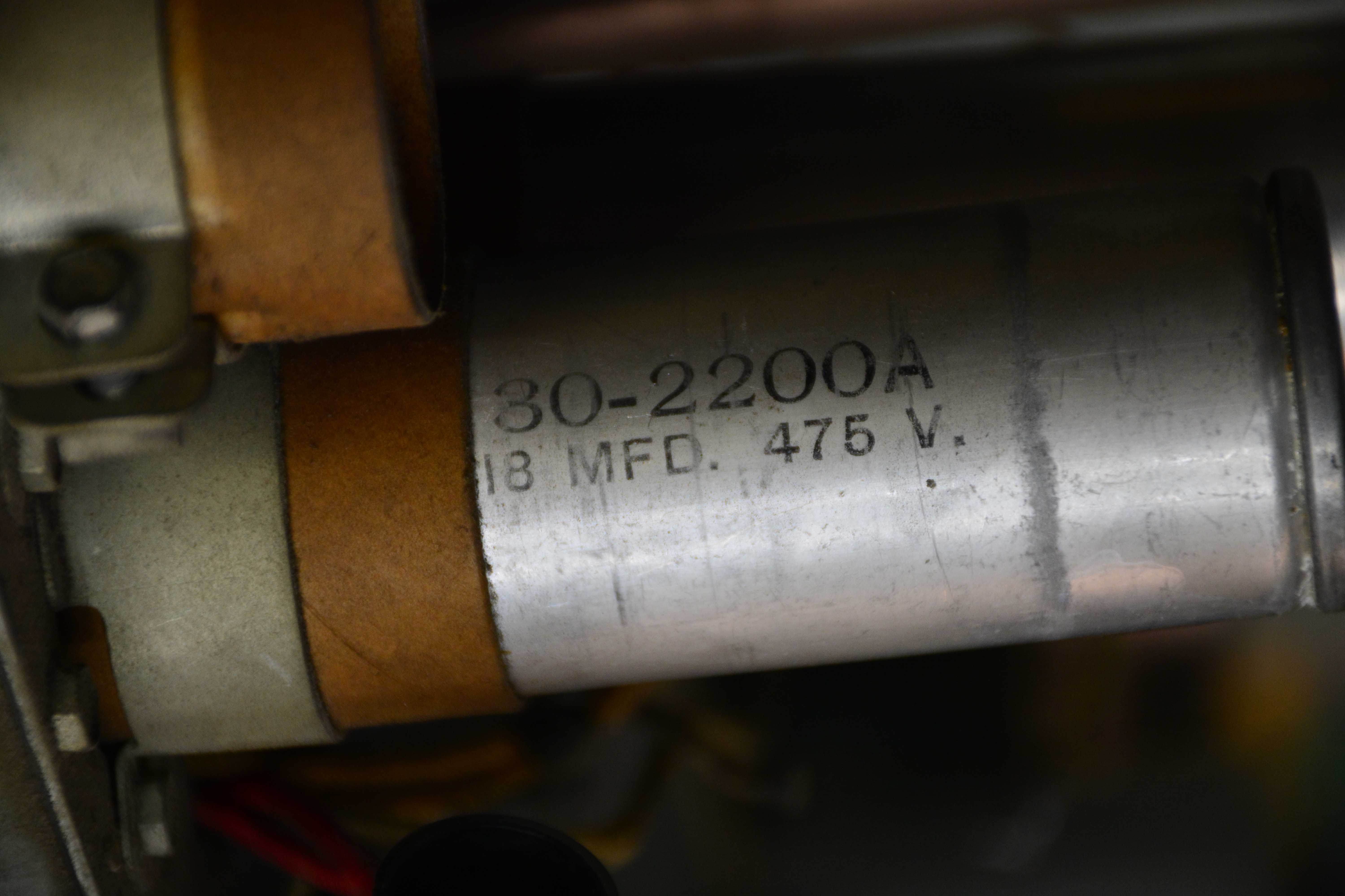
I started digging into the power supply section and found a bit of a discrepancy in the filter caps. The 2 paralleled caps on the output of the rectifier are listed as 8mfd each. Part number is listed as 30-2026. The two caps in my chassis are 30-2200 and are 18mfd each. They don't look like they were changed out and I can find no change notifications in riders. Does anyone have documentation that says 18mfd is correct? Should I stuff with 8 or 18mfd? I'm inclined to go with what was in it unless I can determine that it was a change make by some tech after manufacture.
Posts: 1,199
Threads: 49
Joined: Oct 2017
City: Allendale, MI
Looking at the parts catalog for 1937, I don't find the 30-2200 cap. It appears in the 1939 catalog. Looking at schematics for the 37-690, 38-116, 38-690, I don't find 18mfd caps used in the power supply. I suspect someone changed these early in its history. Did these radios have a slight amount of hum that someone was trying to get rid of? I'm thinking that I will stuff these with 10mfd Solens that I have in stock.
Posts: 27
Threads: 1
Joined: Aug 2018
City: Mississauga
State, Province, Country: Ontario
The larger capacitor may have been for a version of the radio used with 25 Hz power. There is usually a difference in capacitors used with the 60 Hz and 25 Hz versions. The changeover came in the early 1950's.
Posts: 1,199
Threads: 49
Joined: Oct 2017
City: Allendale, MI
I thought the same thing so I checked the model tag and it clearly says 50-60 cycle. Maybe someone brought the radio into a 25 cycle area and had to increase the caps. The PT is the number for 60 cycle radio so if this was the case, they didn't change out the PT. Regardless, I already have the caps stuffed with 10 mfd Solens. The multi section caps are going to be a problem if I use film caps. They won't fit, as others have found out. I may have to resort to one being under the chassis or use electrolytics. I'll probably order some Nichicons. These don't see the full ripple voltage of the first caps in line.
Posts: 1,199
Threads: 49
Joined: Oct 2017
City: Allendale, MI
Posts: 4,928
Threads: 54
Joined: Sep 2008
City: Sandwick, BC, CA
A point of correction, the conversion of 25 cycle to 60 cycle power grids took place in the late 1950s, around 1957-58, aside from some industrial transmission lines, not early 1950s. Most service manual will have a parts list for the 25 cycle versions which will list the extra or amended parts values, Philco liked to add the suffix "A" to the model numbers of 25 cycle sets, like 90A or 20A, I'm not sure if they were still doing this by 1937 or not.
Regards
Arran
Users browsing this thread: 1 Guest(s)
|
|
Recent Posts
|
|
Rogers Majestic R-646
|
| The output 45s are still in push-pull because the transformer secondary winding is still in the grid circuit providing o...RodB — 11:52 AM |
|
Rogers Majestic R-646
|
| Thanks RodB for the help.
But this is not a real solution to this situation, not even a temporary one. Because the firs...Vlad95 — 11:34 AM |
|
Philco Model 16 wiring question
|
|
I was going to check the voltages as you suggested and hooked it up to my dim bulb. It appears I have a short. The bul...bobclausen — 10:34 AM |
|
Rogers Majestic R-646
|
| You can bypass the interstage transformer by disconnecting the primary, connect a load resistor of about 10k - 20k to th...RodB — 09:40 AM |
|
HiFi (Chifi) tube amp build - but my own design.
|
| So, here's Prince on stage halfway through Purple Rain when he stoops down to his tech and says "Rod, pull out that...RodB — 09:17 AM |
|
Rogers Majestic R-646
|
| Today I finished inspecting all the parts. The result is not very pleasing.
The first positive news:
1) The power tr...Vlad95 — 11:40 PM |
|
HiFi (Chifi) tube amp build - but my own design.
|
| Well, found muh culprit. After using socket test adapters and finding voltages all ok, swapping 6V6s, no avail, swapped ...TV MAN — 11:18 PM |
|
HiFi (Chifi) tube amp build - but my own design.
|
| Well, maybe - maybe not :lol: It's been an interesting project so far! Something so simple, yet so cranky. The 1st one ...TV MAN — 05:12 PM |
|
1949 Motorola 5A9M
|
| Haven't thought of Burgess batteres in a while
https://www.radionostalgia.ca/lib/Images/battery/us/burgess1D.jpgi
...Vlad95 — 03:50 PM |
|
Philco Model 16 wiring question
|
| Measure the voltages first, just in case.morzh — 02:19 PM |
|
Who's Online
|
There are currently 913 online users. [Complete List]
» 1 Member(s) | 912 Guest(s)
|
|
|

|
 
|
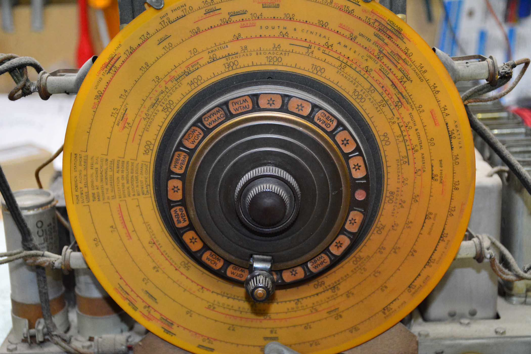


 very exciting!
![[-] [-]](https://philcoradio.com/phorum/images/bootbb/collapse.png)


