Posts: 1,199
Threads: 49
Joined: Oct 2017
City: Allendale, MI
It's really not that different from rewinding the osc coils on older Philcos, just a bit smaller with more taps on the primary. You have to rewind the entire coil as the primary wire also has the green corrosion. But it is still just a single layer on each of the windings. Very doable.
Russ, I would agree with you. There were a lot of spots where the corrosion was evident. As you said, if it's ok now, it won't be for long.
(This post was last modified: 02-12-2019, 01:57 PM by rfeenstra.)
Posts: 2,118
Threads: 112
Joined: Jun 2010
City: Medford OR (OR what?)
Yes. Somebody needed to say that it needs to be rewound completely rather than repaired - which is the normal inclination for most of us.
They used adhesive or wax or paper that was corrosive. What I find interesting is that by overwhelming odds it is always osc coil #2 (appropriate now that I notice ((#2)).
The last one I did was 4 or 5 years ago. I think that I made notes in my Riders'. (As has everyone that has owned the set, 1-20). I find these notes VERY valuable. Did you see the note left on the Stratosphere page? It is in the blog post.
"I just might turn into smoke, but I feel fine"
http://www.russoldradios.com/
(This post was last modified: 02-12-2019, 02:43 PM by Phlogiston.)
Posts: 1,199
Threads: 49
Joined: Oct 2017
City: Allendale, MI
Yes I did, Russ! I make notes too: technical info and comments about the pain level. These are on printouts since I don't have printed Rider's manuals. All of my comments and notes will stay with the radio in an info pack. That means that if I were ever to do another one of these, I might not have the notes! I guess I should make 2 copies.
Posts: 13,776
Threads: 580
Joined: Sep 2005
City: Ferdinand
State, Province, Country: Indiana
...or make your notes electronic in PDF format and keep them on your computer for future use...
--
Ron Ramirez
Ferdinand IN
Posts: 98
Threads: 20
Joined: Nov 2011
City: Tiffin, Ohio
Excellent job on the coil! I have a question, on the 3 primary windings---is it one whole winding with taps soldered on or 3 separate windings wound side by side? I couldn't tell by looking at your repaired coil. Ken
Posts: 1,199
Threads: 49
Joined: Oct 2017
City: Allendale, MI
Yes Ron, I need to do something like that. No need to redo some of the stuff I've already done should I do another same or similar model.
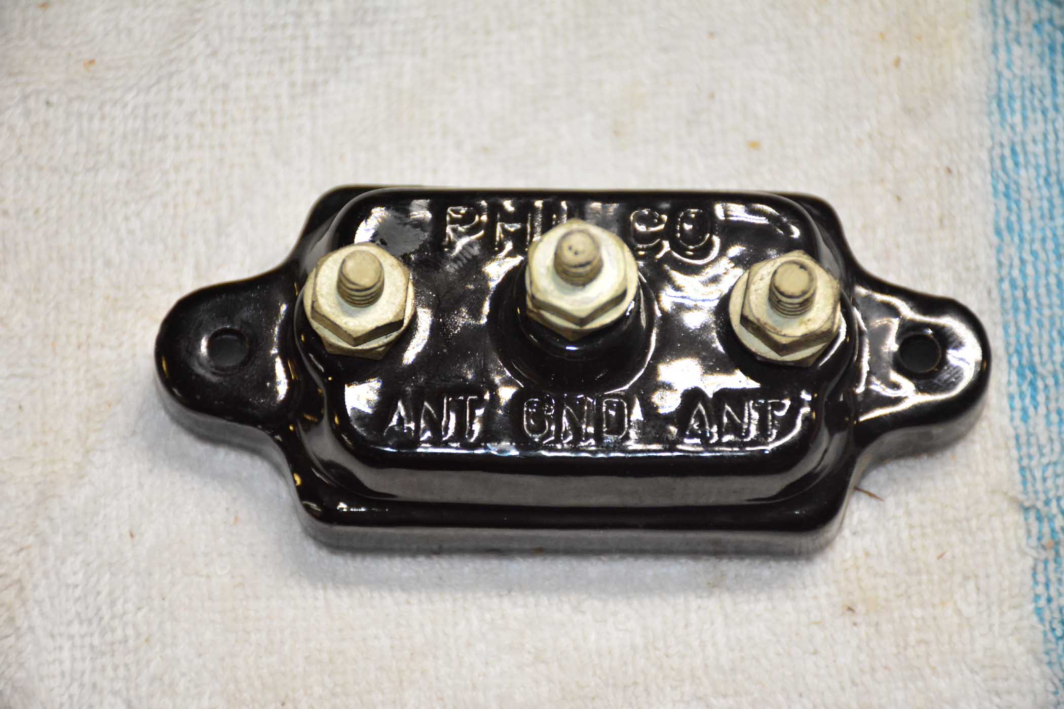
This was mounted in the cabinet. I presume it is a lightning arrestor?
(This post was last modified: 02-12-2019, 06:27 PM by rfeenstra.)
Posts: 1,824
Threads: 114
Joined: Jul 2014
City: Sneedville, TN
Yes, it's a lightning arrestor. It has two antenna terminals and one ground terminal because it is the kind designed to be used with a dipole type antenna like the ones Philco sold rather than a single long wire, or monopole type.
Posts: 1,199
Threads: 49
Joined: Oct 2017
City: Allendale, MI
The radio is reinstalled in the cabinet. This is a good sounding radio. The bass and treble/selectivity controls seem to give a better balance than most of the other radios I've played with. Sensitivity is good and i can pick up a lot of stations on the SW bands.
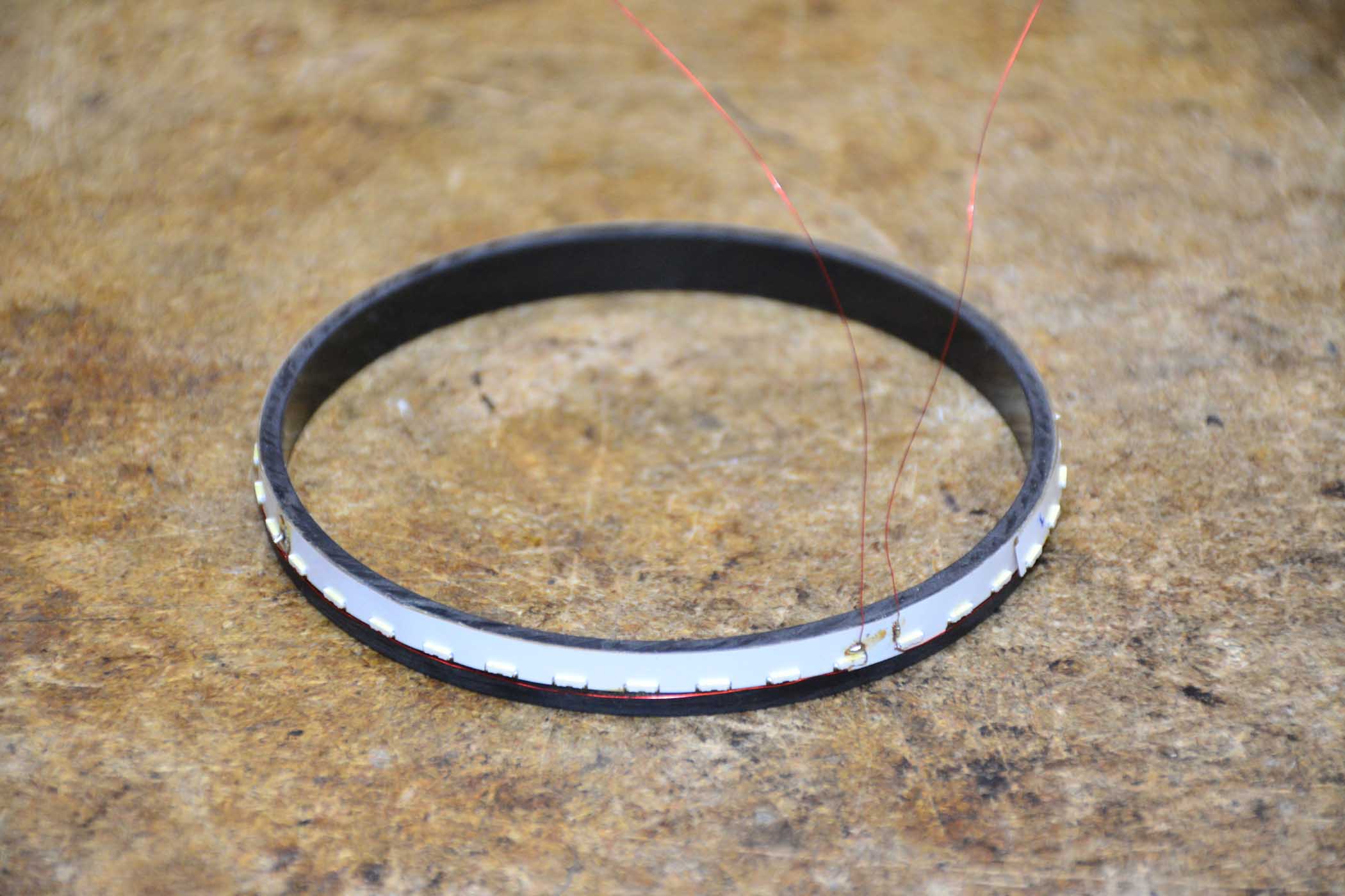
For grins and giggles I've been playing with the lighting of the dial. I'm using the LED strip from the back light of a laptop that I accidentally smashed behind my car seat. The LED strip consists of 40 LED's in 4 series sections. It lights through a 30K resistor from the -60 volt bias/field coil supply. Unfortunately, the color temperature looks to be about 5000K. Way too white so I need to put in an amber or red filter. Right now it is always on. I'll need to put a relay in there if I want it to switch with the magnetic tuning along with the flood lights. I'd rectify the 6.3 volts that feeds the floods but it would not be a high enough voltage to light the 10 LED strings. Brightness can be varied by changing the series resistor value. It'll light with a 75K resistor. The ring is between the shadow mask and the dial, shining through the gap in the dial and into the back side of the station selector ring. Not very original but I kind of like the effect. It's easily removable so I'm not too concerned about originality.
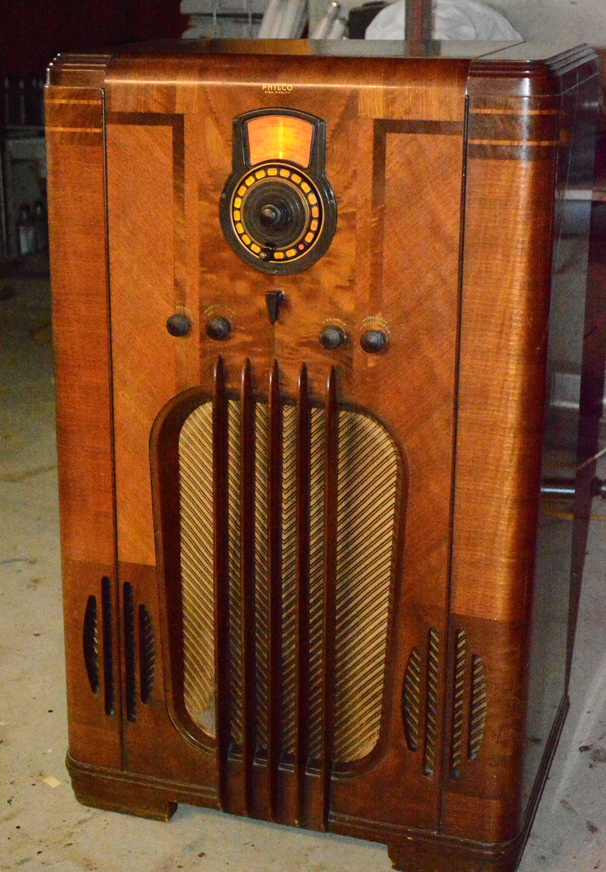
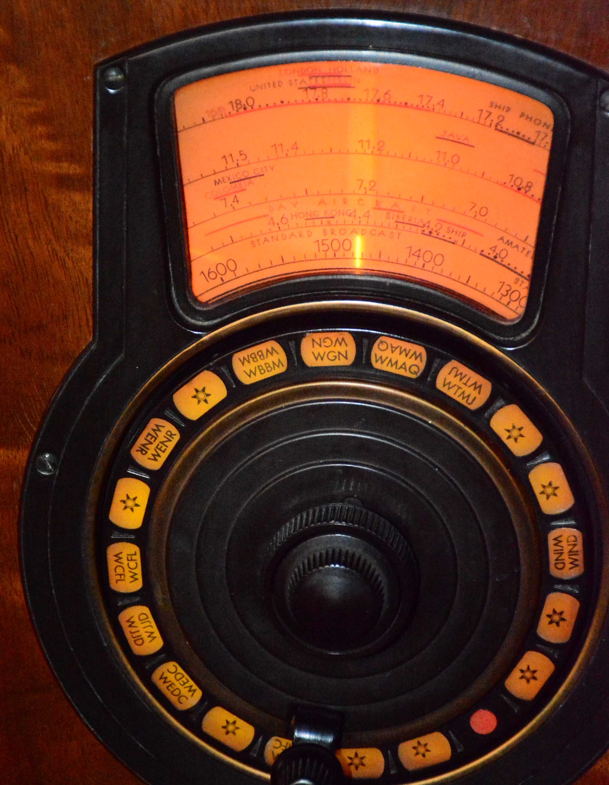
One final question for you finish gurus. This is a very nice cabinet but the finish is slightly checked and the grain is very slightly raised. Has anyone attempted to do a light sanding and then a coat of lacquer to fill in the crazing and cover the grain again? Or is there another way to get back to the smooth, glossy finish it originally had without a complete refinish job? Over the years the finish has lightened up a bit as the color is more brown under the bezel, but I'm not too concerned about that.
Aside from replacing the damaged grille cloth and maybe something with the finish, this project is almost done!
Posts: 2,118
Threads: 112
Joined: Jun 2010
City: Medford OR (OR what?)
You can refinish any cabinet using the methods used for photo-finished cabinets, but you probably do not want to do so.
"I just might turn into smoke, but I feel fine"
http://www.russoldradios.com/
Posts: 33
Threads: 1
Joined: Oct 2016
City: El Cajon, CA
(02-12-2019, 04:26 PM)Kenradio Wrote: Excellent job on the coil! I have a question, on the 3 primary windings---is it one whole winding with taps soldered on or 3 separate windings wound side by side? I couldn't tell by looking at your repaired coil. Ken
I would like to know the answer to this question as well. If you could let us know that would be great. It is difficult to tell in the picture.
Posts: 1,199
Threads: 49
Joined: Oct 2017
City: Allendale, MI
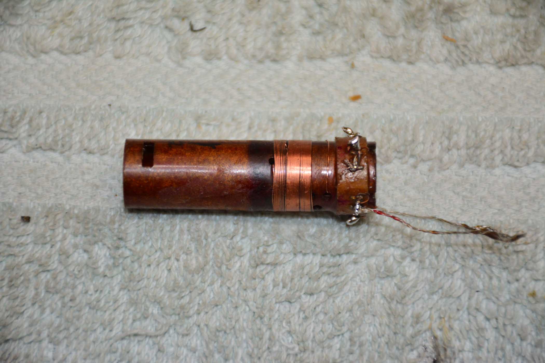
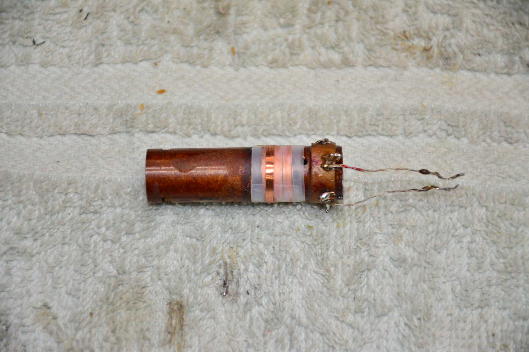
The primary winding is continuous with 2 taps. There is a hole in the form where the tap goes inside the form up to the terminal. The tap is not soldered on to the winding, instead the end of the first winding goes up to the terminal then back down to the hole and the second winding then continues. Same with the next tap. I guess you could say that is is 3 separate windings laid end to end or side by side. So, to confuse matters, there is a hole in the form for the 2 ends of the winding, and for the 2 taps. The secondary wires go to the terminals external as you can see on the photo. Hope that helps! (Sorry Kenradio, I missed your previous post!)
Rob
An addition: Here are a couple of photos of the coil in process. You will notice that the last section of the primary does not lay nicely. this is because I found a cross over in the wire and I had to unwind and then rewind by hand instead of on my coil winding setup. This may also account for the fact that I needed to add a bit of capacitance to the compensating capacitor.
(This post was last modified: 02-14-2019, 06:03 PM by rfeenstra.)
Posts: 13,776
Threads: 580
Joined: Sep 2005
City: Ferdinand
State, Province, Country: Indiana
Very neat! What sort of coil winding setup do you have?
--
Ron Ramirez
Ferdinand IN
Posts: 1,199
Threads: 49
Joined: Oct 2017
City: Allendale, MI
Posts: 13,776
Threads: 580
Joined: Sep 2005
City: Ferdinand
State, Province, Country: Indiana
Looks good. 
Maybe this is why my attempts at rewinding those band 2 coils from 1937-38 5-band Philcos never worked - I do my coil winding the hard way...by hand.
--
Ron Ramirez
Ferdinand IN
Posts: 2,118
Threads: 112
Joined: Jun 2010
City: Medford OR (OR what?)
I did mine by hand. At only 36 turns, the coil winder takes too long to set up compared to winding by hand.
I also did not use the separator, rather winding right on top. Maybe that accounts for the decreased capacitance.
"I just might turn into smoke, but I feel fine"
http://www.russoldradios.com/
(This post was last modified: 02-14-2019, 08:05 PM by Phlogiston.)
Users browsing this thread: 1 Guest(s)
|
|
Recent Posts
|
|
Rogers Majestic R-646
|
| The output 45s are still in push-pull because the transformer secondary winding is still in the grid circuit providing o...RodB — 11:52 AM |
|
Rogers Majestic R-646
|
| Thanks RodB for the help.
But this is not a real solution to this situation, not even a temporary one. Because the firs...Vlad95 — 11:34 AM |
|
Philco Model 16 wiring question
|
|
I was going to check the voltages as you suggested and hooked it up to my dim bulb. It appears I have a short. The bul...bobclausen — 10:34 AM |
|
Rogers Majestic R-646
|
| You can bypass the interstage transformer by disconnecting the primary, connect a load resistor of about 10k - 20k to th...RodB — 09:40 AM |
|
HiFi (Chifi) tube amp build - but my own design.
|
| So, here's Prince on stage halfway through Purple Rain when he stoops down to his tech and says "Rod, pull out that...RodB — 09:17 AM |
|
Rogers Majestic R-646
|
| Today I finished inspecting all the parts. The result is not very pleasing.
The first positive news:
1) The power tr...Vlad95 — 11:40 PM |
|
HiFi (Chifi) tube amp build - but my own design.
|
| Well, found muh culprit. After using socket test adapters and finding voltages all ok, swapping 6V6s, no avail, swapped ...TV MAN — 11:18 PM |
|
HiFi (Chifi) tube amp build - but my own design.
|
| Well, maybe - maybe not :lol: It's been an interesting project so far! Something so simple, yet so cranky. The 1st one ...TV MAN — 05:12 PM |
|
1949 Motorola 5A9M
|
| Haven't thought of Burgess batteres in a while
https://www.radionostalgia.ca/lib/Images/battery/us/burgess1D.jpgi
...Vlad95 — 03:50 PM |
|
Philco Model 16 wiring question
|
| Measure the voltages first, just in case.morzh — 02:19 PM |
|
Who's Online
|
There are currently 1110 online users. [Complete List]
» 2 Member(s) | 1108 Guest(s)
|
|
|

|
 
|


![[-] [-]](https://philcoradio.com/phorum/images/bootbb/collapse.png)


